RuggedMC™ RMC30 Installation Guide RuggedCom Inc. 300 Applewood Crescent, Concord, Ontario Canada L4K 5C7 Web: http://www.ruggedcom.
Copyright COPYRIGHT © 2010 RuggedCom Inc. ALL RIGHTS RESERVED Dissemination or reproduction of this document, or evaluation and communication of its contents, is not authorized except where expressly permitted. Violations are liable for damages. All rights reserved, particularly for the purposes of patent application or trademark registration. This document contains proprietary information, which is protected by copyright. All rights are reserved.
Federal Communications Commission Radio Frequency Interference Statement This equipment has been tested and found to comply with the limits for a Class A digital device pursuant to Part 15 of the FCC Rules. These limits are designed to provide reasonable protection against harmful interference when the equipment is operated in a commercial environment.
Table of Contents 1 2 3 4 5 6 Product Overview.......................................................................................................................................5 1.1 RMC30 Front Panel Description.........................................................................................................6 1.2 RMC30 Side and Bottom View............................................................................................................8 Installation.................................
1 Product Overview INTRODUCTION The RuggedServer™ RMC30 is an industrially hardened, 2-port serial device server that has been specifically designed to operate in electrically harsh and climatically demanding environments. The RMC30 allows you to communicate with virtually any serial device via Ethernet providing simple and reliable network connectivity.
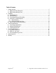
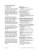
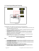
1.1 RMC30 Front Panel Description Reset Push Button Power & Alarm LED Indicators 10Base Tx Ethernet Port RS232/422/485 Connector Transmit(Tx) and Receive(Rx) LEDs Power Supply Connector Drawing 1 - RMC30 Front Panel Description The RMC30 LED definitions are as follows: LED Activity Description Power Solid (Green) Alarm Solid (Red) Link Solid (Yellow) Act Blinking (Yellow) Transmitting/receiving Ethernet data.
1.
2 Installation 2.
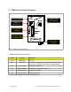
2.2 Panel Mounting With the use of an optional panel-mount adapter, the RuggedMCTM series of media converters can be panel mounted. Drawing 4 shows an example of an RMC unit panel mounted using the optional panel mount adapter. The panel mount adapter can be secured to a panel with three screws. The RuggedMCTM product is easily mounted onto the panel mount adapter via the two metal clips on either side of the unit, and a single screw located on the bottom.
2.3 Power Supply Wiring and Grounding Drawing 5 - RuggedMCTM Power Supply Inputs The RuggedMCTM power supply inputs are identical and are connected as follows: 1. +/L = DC (+) / AC (Hot) is connected to the positive (+) terminal if the power source is DC or to the (Hot) terminal if the power source is AC. 2. -/N = DC (-) / AC (Neutral) is connected to the negative (-) terminal if the power source is DC or to the (Neutral) terminal if the power source is AC. 3.
2.4 Serial Ports – Signal Description The RMC30 is equipped with a seven-terminal phoenix style connector. This connector can accommodate one RS232 connection, and one RS485/422 connection. Drawing 6 shows the connections for RS232, RS485, and RS422 communications. The following sections describe installation details for respective ports.
2.4.1 RS232 Data Port The RMC30 is equipped with a single EIA/TIA RS232 compliant port, consisting of three terminals: Transmit, Receive, and Common. The RS232 port is intended for point-to-point applications only. The EIA/TIA guidelines for RS232 communications include (but are not limited to) the following: 1. To minimize the effects of ambient electrical noise, shielded cabling is recommended. 2. Reliable communications within 15m. Greater distances are possible. 3.
2.4.2 RS422 and RS485 Data Ports The RMC30 is equipped with a single RS485 / RS422 data port. In half duplex mode (See section 2.5 for RMC30 configuration) the RS485 connections (Rx +, Rx -, COM) should be connected. In full-duplex mode the RS422 connections (Rx+, Rx -, Tx+, Tx-, COM) should be connected. Both RS485 and RS422 can accommodate multi-drop networks, for master-slave serial network communications. For both RS485 / RS422 connections, the following general guidelines should be followed: 1.
Drawing 8 - Conceptual RS485 wiring diagram RuggedCom® 14 RuggedMC™ RMC30 Installation Guide Rev 105
2.5 RMC30 Quick Start Recommendations The following is an excerpt from the RMC30 User's Guide. It is included to aid those users experienced with communications equipment that may wish to attempt to configure the server without fully reading the guide. We recommend review of the User Guide for a complete understanding of the RMC30 serial device server. 1.
3 Technical Specifications 3.1 Power Supply Specifications Power Supply Type Minimum Input Maximum Input 24 VDC 48 VDC HI (88/300 VDC) 1 HI (120/240 VAC) 1 18 VDC 36 VDC 88 VDC 85 VAC 36 VDC 72 VDC 300 VDC 264 VAC Internal Fuse Rating 3.15A(T) 2 3.15A(T) 2 3.15A(T) 2 Maximum Power Consumption 3W Notes: 1 – This is the same power supply for both AC and DC.
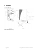
3.2 Mechanical Specifications Drawing 9 - RMC30 Mechanical Dimensions Parameter Dimensions Weight Enclosure RuggedCom® Value 4.30 x 2.40 x 3.30 inches Comments (Length x Width x Height) (110) x (61) x (84) mm 1.
3.3 Operating Environment Parameter Range Ambient Operating Temperature -40 to 85°C Ambient Relative Humidity Ambient Storage Temperature RuggedCom® 5% to 95% Comments Ambient Temperature as measured from a 30cm radius surrounding the center of the RuggedMCTM enclosure.
4 Type Test Specifications 4.1 IEC 61850-3 Type Tests IEC 61850-3 EMI TYPE TESTS Test Description IEC 61000-4-2 ESD Test Levels Severity Levels Enclosure Contact +/- 8kV 4 Enclosure Air +/- 15kV 4 IEC 61000-4-3 Radiated RFI Enclosure ports 20 V/m x IEC 61000-4-4 Burst (Fast Transient) Signal ports +/- 4kV @ 2.5kHz x D.C. Power ports +/- 4kV 4 A.C. Power ports +/- 4kV 4 Earth ground ports1 +/- 4kV 4 Signal ports +/- 4kV line-to-earth, +/2kV line-to-line 4 D.C.
D.C. Power ports 30V Continuous, 300V for 1s 4 IEC 61000-4-17 Ripple on D.C. Power Supply D.C. Power ports 10% 3 IEC 60255-5 Dielectric Strength Signal ports 2kVac (Fail-Safe Relay output) N/A D.C. Power ports 1.5kVdc N/A A.C. Power ports 2kVac N/A Signal ports 5kV (Fail-Safe Relay output) N/A D.C. Power ports 5kV N/A A.C. Power ports 5kV N/A Test Levels Severity Levels Enclosure Contact +/- 8kV N/A Enclosure Air +/- 15kV N/A IEC 60255-5 H.V. Impulse 4.
4.
5 Agency Approvals Agency CSA, CE FCC CISPR FDA/CDRH IEC/EN Standards CSA C22.2 No. 60950, UL 60950, EN 60950 EN 61000-6-2 FCC Part 15, Class A EN55022, Class A 21 CFR Chapter 1, Subchapter J EN60825-1:1994 + A11:1996 + A2:2001 Comments Approved Approved Approved Compliant Compliant 6 Warranty RuggedCom warrants this product for a period of five (5) years from date of purchase. For warranty details, visit http://www.ruggedcom.com/ or contact your customer service representative.