
Basic Documentation

93/256
Siemens Modular Heating Controller RMH760B CE1P3133en
Building Technologies 7 Heat demand and heat requests 2017-09-29
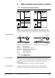
Both outputs are always available, even if no main controller has been configured.
• If only a boiler is configured, the requests received will be forwarded to the boiler
• If neither a boiler nor a main controller is configured, the requests received from the
heat distribution zone will be forwarded
For notes on configuration, refer to section 8.2 "Configuration".
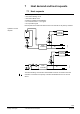
7.3 Heat demand transformer
Heat demand transformers are available both with the main controller and the primary
controller. They receive and handle the heat request signals from:
• The individual room radiators (RXB…)
• The individual room air heating coils (RXB…)
• Air handling plant (RMU…)
If the main controller is not activated, the boiler can make use of the main controller’s
heat demand transformer.
The transformers convert the position heat request signals (in %) into heat demand
signals with a flow temperature setpoint.
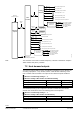
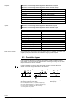
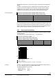
The following example of an air handling plant shows this.
T
T
T
T
RMH760B
3131B05
Room unit
(in reference room)
Central
air handling
DHW
precontrol
Chilled water
precontrol
Air supply area
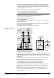
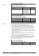
RMH760B
RMU...
0...100 %
3131B06
Precontrol
heating
Ventilation
Precontrol
refrigeration
Heat demand
transformer
Refrigeration
demand
transformer
The heat demand transformers calculate a flow temperature setpoint based on the
valve position of the air handling plant(s).
If the primary controller is capable of delivering an outside temperature signal, the flow
temperature setpoint according to the heating curve will be used as the start value. If no
outside temperature signal is available, the start value used will be the flow temperature
at curvepoint 1.
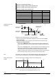
This flow temperature start value is matched to the actual heat demand in a way that
the valve position of the heat consumer with the greatest heat demand is 90 %.
• If the valve position is >90 %, the flow temperature will be increased
• If the valve position is <90 %, the flow temperature will be decreased
The maximum flow temperature readjustment can be parameterized.
To ensure that minimum opening travel of the valve will not generate a demand for
heat, a switch-on or switch-off threshold can be defined. The factory settings are as
follows:
• A demand for heat will be calculated only when the valve positions are >10 %
• When the valve positions of all consumers are <5 %, the demand for heat will be
suppressed again
Example: Air handling
plant