
Basic Documentation

35/256
Siemens Modular Heating Controller RMH760B CE1P3133en
Building Technologies 3 Commissioning 2017-09-29
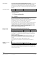
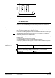
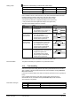
G
G
G0
X...
G0
N
3140A05
AC 24 V
M
F...
∆
p
X...
M
F...
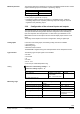
Digital signals cannot be monitored.
3.4 Wiring test
A wiring test can be made with all connected peripheral devices. We recommend to
conduct this test after the configuration and the settings have been made.
The current states are indicated at the inputs.
The aggregates connected to the outputs (pumps, actuators, etc. ) or messages (e.g.
for conventional controllers) can be switched on and off.
In the case of modulating outputs, a signal can be delivered in the relevant value range.
The application is deactivated during the wiring test. Th
e outputs are in a defined off
state; safety
-related functions are deactivated.
When making the wiring test, the inputs and outputs are to be checked for the following
types of errors:
• Connection fault (wires have been mixed up)
• Position fault (wires of sensor or actuator have been mixed up)
• Discrepancy between the actual type of connection and the controller’s configuration
(e.g. LG-Ni 1000 in place of DC 0…10 V)
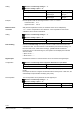
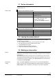
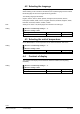
Main menu > Commissioning > Wiring test > Heating circuit 1 (or 2 or 3) > Inputs
Operating line
Adjustable values / display / remarks
Actual value flow temp
Display of the current measured value
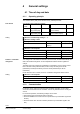
Main menu > Commissioning > Wiring test > Heating circuit 1 (or 2 or 3) > Outputs
Operating line
Positions
Heating circuit pump
Off / On
Fault handling
Inputs
Outputs
Example on the basis of
heating circuit 1