
Basic Documentation

25/256
Siemens Modular Heating Controller RMH760B CE1P3133en
Building Technologies 3 Commissioning 2017-09-29
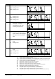
Plant type
Description
Plant diagram
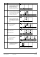
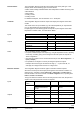
H5-6
N1:
A2(1):
A2(2):
Heating circuit
Heating circuit
Heating circuit
A2(2)A2(1)
3133S41
N1
N.X1
N.Q3
N.Q1/Q2
N.X3
H5-6
A2.X1
A2.Q3
A2.Q1/Q2
A2.X3
A2
.X1
A2.Q3
A2.Q1/Q2
A2.X3
N.X2
H5-7
A3:
N1:
A2(1):
A2(2):
DHW circuit (DHW 3)
Heating circuit
Heating circuit
Heating circuit
A2(1)N1 A2(2)
3133S42
A3
N.X1
N.Q3
N.Q1/Q2
N.X3
A2.X1
A2.Q3
A2.Q1/Q2
A2.X3
A2.X1
A2.Q3
A2.Q1/Q2
A2.X3
A3.X2
A3.X4
H5-7
N.X2
A3.Q1/Q2
A3.Q3
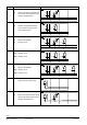
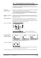
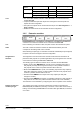
H6-1
N1: Direct DHW consumption via heat
exchanger connected to
uncontrolled main flow, with
circulating pump (DHW 6)
N1
3133S44
N.Y1
N.Q5
N.X5
H6-1
H6-3
N1: DHW circuit (DHW 6) and
weather-compensated heating
circuit control via heat exchangers
with 2-port valve in the primary
return
N1
3133S45
N.Y1
N.Q5
N.X5
H6-3
N.X1
N.Q3
N.Q1/Q2
N.X3
N.X2
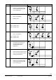
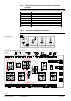
H6-5
N1:
A2:
DHW circuit (DHW 6) and heating
circuit
Heating circuit
A2N1
3133S46
N.Y1
N.Q5
N.X5
H6-5
N.X1
N.Q3
N.Q1/Q2
N.X3
A2.X1
A2.Q3
A2.Q1/Q2
A2.X3
N.X2
H6-7
N1:
A2(1):
A2(2):
DHW circuit (DHW 6) and heating
circuit
Heating circuit
Heating circuit
A2(1)N1 A2(2)
3133S47
N.Y1
N.Q5
N.X5
H6-7
N.X1
N.Q3
N.Q1/Q2
N.X3
A2.X1
A2.Q3
A2.Q1/Q2
A2.X3
A2.X1
A2.Q3
A2.Q1/Q2
A2.X3
N.X2
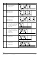
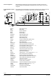
N.
Connection terminals of heating controller N1
A2.
Connection terminals of heating circuit module RMZ782B
A2(1)
Connection terminals of the first heating circuit module RMZ782B, if 2 heating circuit modules are used
A2(2)
Connection terminals of the second heating module RMZ782B, if 2 heating circuit modules are used
A3.
Connection terminals of the DHW module RMZ783B
Q1
Relay terminals, consisting of Q11, Q12 and Q14 (e.g. actuator)
Q2
Relay terminals, consisting of Q23 and Q24 (e.g. actuator)
Q3
Relay terminals, csisting of Q33 and Q34 (e.g. heating circuit pump)
Q4
Relay terminals, consisting of Q41, Q42 and Q44 (e.g. storage tank charging pump)
Q5
Relay terminals, consisting of Q53 and Q54 (e.g. boiler pump)
X1
Configurable input for main controlled variable (e.g. flow temperature)
X2
Configurable input for auxiliary controlled variable (e.g. outside temperature)
X3
Configurable input for auxiliary controlled variable (e.g. return temperature)
X4
Configurable input for auxiliary controlled variable (e.g. sensor for secondary storage tank flow)
X5
Configurable input for auxiliary controlled variable (e.g. sensor for secondary storage tank flow)