
Basic Documentation

247/256
Siemens Modular Heating Controller RMH760B CE1P3133en
Building Technologies 17 Appendix 2017-09-29
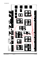
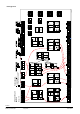
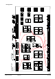
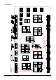
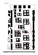
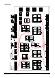
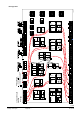
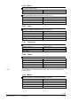
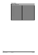
Plant type H6-7
a a a a d da
Q Q
x x
1
2
x x
3
4
0...1 0 V
Y Q
d
d
B
d
B
V
Q
2
)
1
)
3
P
R
1
Q
R
2
Q
d
d d
Q
Y Q
a a a a d da
Q
0...1 0 V
Y
Q
d
d
B
d
B
V
Q
2
)
1
)
3
P
a
R
1
Q
R
2
Q
d d
Q
a a a a d da
Q
0...1 0 V
Y Q
d
d
B
d
B
V
Q
2
)
1
)
3
P
a
R
1
Q
R
2
Q
d d
Q
RMH76
0
N .X5
x
N. X6
x
N.X4
x
N.X3
x
N.X2
x
N.X1
x
A7.X3
x
A7. X4
x
A7 .X2
x
A7.X1
x
RMZ78
9 (2)
A9.X6
x
A9 .X5
x
A9. X3
x
A9 .X4
x
A9 .X2
x
A9. X1
x
RMZ789 (1)
(
)
A2.X3
x
A2 .X2
x
A2.X1
x
A2.X3
x
A2 .X2
x
A2.X1
x
A 3.X3
x
A3.X4
x
A3. X2
x
A 3.X1
x
RMZ78
2 (2)
RMZ78
3
RMZ78
7
A9
.X6
x
A9.X5
x
A9. X3
x
A9 .X4
x
A 9.X2
x
A9. X1
x
a d d d
Q
d d
B
d
B
V
Q
1
)
DC 0...1 0 V
a
0...1 0 V
Y
a
2
)
3
P
a d d d
Q
d d
B
d
B
V
Q
1
)
D C 0 ...10 V
a
0...1 0 V
Y
a
2
)
3
P
i i i i
1
2
3
4
1. 2.
da da ddd
Q Q Q
d
Q
d
B
d
B
V
Q
a
0...1 0 V
Y
0...1 0 V
Y
2
)
2
)
1
)
3
P
3
P
Y
d d d
a xa
Q
a
a d
0...1 0 V
Y
2
)
3
P
N.Y1
Y
N. Q4
Q
N. Q1
Q
N.Q2
Q
N.Q3
Q
N. Q5
Q
A9
.Q
2
Q
A9
.Q
3
Q
A9
.Q
4
Q
A9
.Q
1
Q
A7
.Q
1
Q
A
7
.Q
2
Q
A
7
.Q
3
Q Q
A7
.Q
5
N
1
N
2
N
1
N
2
N
3
N
4
N.Y2
Y
A9
.Y
1
Y
A9
.Y
2
Y
A9
.Q
2
Q
A9
.Q
3
Q
A9
.Q
4
Q
A9
.Q
1
Q
N
1
N
2
N
3
N
4
A9
.Y
1
Y
A9
.Y
2
Y
3
P
3
P
3
P
3
P
3
P
A2. Q2
Q
A2. Q3
Q
N
1
N
2
A2. Y1
Y
3
P
A2. Q2
Q
A2. Q3
Q
N
1
N
2
A2. Y1
Y
3
P
A3.Q2
Q
A3. Q3
Q
A3
.Q
5
Q
N
1
N
2
A3.Y1
Y
3
P
A3
.Q
4
Q
3
P
RMZ78
2 (1)
V
a a a
d
a a
d dd
Q
Y
3
P
Q QY
3
P
Q Q
V
d d
B
d
0...1 0 V
2
)
B
0...1 0 V
2
)
1
)
B
1
)
B
V
dd d
B
da
Q Q
B
0...1 0 V
Y
2
)
3
P
Q
dd
1
)
a
A2.Q1
Q
A2.Q1
Q
A3. Q1
Q
1 2 21
x x x x
A B
3
x
Q
d
C
1 2 21
x x x x
A
B
3
x
Q
d
C
1 2 21
x x x x
A
B
3
x
Q
d
C
1 2 21
x x x x
A
B
3
x
Q
d
C
Q
a
a
d
A
-
B
Q
a a
d
A
-
B
x x xxx x x
...
...
X
1
2
3
4
X X X
.
Flow
Return
Room
Room rel.
Timer
Room abs.
Operating mode
clo se
open
Relay 1
Relay 2
Hea
ting
ci
rcu
it 1
HC
-
pump
Fault button
Heating limit
Heating
Heat demand
Operating mode
Outside
Flow
Return
Room
Room rel.
Room abs.
Operating mode
Timer
open
clo se
HC
-
pump
Heating limit
Operating mode
Flow
Return
Room
Room rel.
Room abs.
Outside
Operating mode
Timer
clo se
open
Heating limit
Operating mode
HC
-
pump
He a
ting
ci
rcu
it 3
He a
ting
ci
rcu
it 2
Heat requis.
Fr o st
Flow
Return
clo se
open
Main
pum
p
Disp la y 1
Disp la y 8
Win d
Solar
Outside
Legionella
function relay
P r
ima
ry
Flo w
Return
Flo w
Se
con
dary
Con-
su
m
er
Ci
rc u
-
la
ti
o
n
Ta
nk
Operating mode
clo se
open
clo se
open
clo se
open
Mai
nta
in.
t
em
p.
Flue gas
R
e
l
e
a
s
e
Flue gas m ode
.
Burner
Boiler
Return
Burner
Shutoff valve
B
oile
rp.
Bypa
ssp
.
(Water shortage) 1
(Overpressure) 2
(Underpressure) 3
P
um
p
f
un
ct
:
Boi
le r
M
odul
ati
ng
S
tage
clo se
open
Setpoint comp.
clo se
open
M
BRT
Flow
Return
Heating
Fr o st
Pri
mar
y c
ont
roll
er
H
e
a
t
r
e
q
u
i
s
.
Sys
tem
pum
p
clo se
open
top
bottom
Flo w
Forced charging
4
Ex
ten
sion
mo
dul
es
1
) 6
Single
or tw
in pump
s
2) 6
Contr
ol outp
uts (DC
0...1
0 V or
3-posi
tioning
)
3-Posi
tioning
ou tpu
t in pa
irs Q1
/Q2, Q3
/Q4
Co
nfigur
ation D
iagr
am
RMH7
60B
Maximum c
onfiguration:
Pl
ant typ
e
M
is
c
el
la
n
eo
us
M
ai
n
c
on
t
ro
ll
e
r
Fau
lts
Co
unter
DH
W
P
rima
ry
Return
Flow signal
Flow
clo se
open
S
econ
dar
y
= fro
m
= t
o
3133W01_H_en_a
Com
par
ato
r 2
Comp
arator
1
Log
ic 1
Lo
gi k
2
L
og
i
k
3
Lo
gi k
4
Tr
end
H6-
7
H6-
7