
Basic Documentation

246/256
Siemens Modular Heating Controller RMH760B CE1P3133en
Building Technologies 17 Appendix 2017-09-29
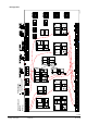
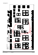
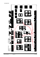
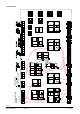
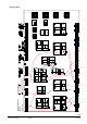
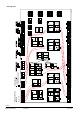
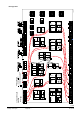
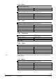
Plant type H5-7
a a a
a d da
Q Q
x x
1
2
x x
3
4
0...1 0 V
Y
Q
d
d
B
d
B
V
Q
2
)
1
)
3
P
R1
Q
R2
Q
d
d d
Q
Y Q
a a a a d d
a
Q
0...1 0 V
Y
Q
d
d
B
d
B
V
Q
2
)
1
)
3
P
a
R1
Q
R
2
Q
d d
Q
a a a a d d
a
Q
0...1 0 V
Y Q
d
d
B
d
B
V
Q
2
)
1
)
3
P
a
R
1
Q
R
2
Q
d d
Q
RMH
760
N .X5
x
N. X6
x
N.X4
x
N.X3
x
N.X2
x
N.X1
x
A7.
X3
x
A7
. X4
x
A7 .X2
x
A7.X1
x
RMZ789 (2)
A9.X
6
x
A9
.X5
x
A
9.X3
x
A9 .X4
x
A9 .X
2
x
A9
. X1
x
RMZ789 (1)
( )
A2.X3
x
A2 .X2
x
A2.X1
x
A2.X3
x
A2 .X2
x
A2.X1
x
A 3.X3
x
A3.X4
x
A3. X2
x
A 3.X1
x
RMZ7
82 (2)
RMZ783 RMZ787
A9 .X6
x
A9.X5
x
A9.
X3
x
A9
.X4
x
A 9.X2
x
A9. X1
x
a
d d d
Q
d d
B
d
B
V
Q
1
)
DC 0...1 0 V
a
0...1 0 V
Y
a
2
)
3
P
a d d d
Q
d d
B
d
B
V
Q
1
)
D C 0 ...10 V
a
0...1 0 V
Y
a
2
)
3
P
i i i i
1
2
3
4
1. 2.
da da ddd
Q Q Q
d
Q
d
B
d
B
V
Q
a
0...1 0 V
Y
0...1 0 V
Y
2
)
2
)
1
)
3
P
3
P
Y
d d d
a xa
Q
a
a d
0...1 0 V
Y
2
)
3
P
N
.Y
1
Y
N.
Q
4
Q
N
.Q
1
Q
N.
Q
2
Q
N
.
Q3
Q
N
.Q
5
Q
A9.Q2
Q
A9.Q3
Q
A9.Q4
Q
A9.Q1
Q
A7. Q1
Q
A
7.Q2
Q
A
7.Q3
Q Q
A7.Q5
N1 N2 N
1 N
2
N
3 N4
N
.Y
2
Y
A9.Y1
Y
A9.Y2
Y
A9. Q2
Q
A9.Q3
Q
A9.Q4
Q
A9. Q1
Q
N
1 N2 N3 N
4
A9.Y1
Y
A9.Y2
Y
3
P
3
P
3
P
3
P
3
P
A2
.
Q2
Q
A
2
.Q
3
Q
N
1
N
2
A2
.Y
1
Y
3
P
A2
.
Q2
Q
A
2
.Q
3
Q
N1 N
2
A
2.
Y
1
Y
3
P
A3.Q2
Q
A3. Q3
Q
A3.Q5
Q
N
1
N
2
A3.Y1
Y
3
P
A3.Q4
Q
3
P
RMZ7
82 (1)
V
a a a
d
a a
d dd
Q
Y
3
P
Q QY
3
P
Q Q
V
d d
B
d
0...1 0 V
2
)
B
0...1 0 V
2
)
1
)
B
1
)
B
V
dd
d
B
da
Q Q
B
0...1 0 V
Y
2
)
3
P
Q
dd
1
)
a
A2
.Q
1
Q
A
2.
Q
1
Q
A3. Q1
Q
1 2 21
x x x x
A B
3
x
Q
d
C
1 2 21
x x x x
A
B
3
x
Q
d
C
1 2 21
x x x x
A B
3
x
Q
d
C
1 2 21
x x x x
A
B
3
x
Q
d
C
Q
a
a
d
A - B
Q
a a
d
A - B
x x xx
x x x
...
...
X
1
2
3
4
X X X
.
Flow
Return
Room
Room rel.
Timer
Room abs.
Operating mode
clo se
open
Relay 1
Relay 2
He
ati
ng c
irc
uit
1
HC-
pum
p
Fault button
Heating limit
Heating
Heat demand
Operating mode
Outside
Flow
Return
Room
Room rel.
Room abs.
Operating mode
Timer
open
clo se
HC-
pum
p
Heating limit
Operating mode
Flow
Return
Room
Room rel.
Room abs.
Outside
Operating mode
Timer
clo se
open
Heating limit
Operating mode
HC-
pump
He ating circuit 3He ating circuit 2
Heat
re
qui
s.
Fr o st
Flow
Return
clo se
open
Main
pump
Disp la y 1
Disp la y 8
Win d
Solar
Outside
Legionella
function relay
P rimary
Flo w
Return
Flo w
Sec
ond
ary
C
on-
sum
er
C
irc
u-
l
ati
on
Tan
k
Operating mode
clo se
open
clo se
open
clo se
open
Maintain.
tem
p.
Flue gas
R
e
le
a
s
e
Flue gas m ode
.
Burner
Boiler
Return
Burner
Shutoff valve
Boilerp.
Bypassp.
(Water shortage) 1
(Overpressure) 2
(Underpressure) 3
Pump funct:
B
oil
er
Mo
dul a
ti n
g
St
age
clo se
open
Setpoint comp.
clo se
open
MB
RT
Flow
Return
Heating
Fr o st
Primar y controller
H
e
a
t
r
e
q
u
i
s
.
Sys
tem
pump
clo se
open
top
bottom
Flo w
Forced charging
4
Exten
sion mod
ules
1) 6 Single or twin pumps
2) 6 Control outputs (DC 0...10 V or 3-positioning)
3-Posi tioning ou tput i n pairs Q1/Q2, Q3/Q4
C
onfigur
ation
Diagram
RMH760B
Maximum conf
iguration:
Plan
t type
Mis
ce l
lan
eous
Ma
in
con
trol
ler
Faults
Counter
DHW
Primary
Return
Flow signal
Flow
clo se
open
Secondary
= from
= to
3133W01_H_en_a
Comparator 2
Com
par
ator
1
Logi c 1
Log
ik
2
Lo
gi k
3
L
ogi
k 4
Trend
H5-7