
Basic Documentation

241/256
Siemens Modular Heating Controller RMH760B CE1P3133en
Building Technologies 17 Appendix 2017-09-29
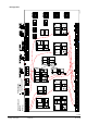
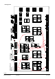
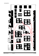
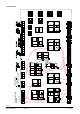
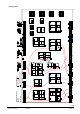
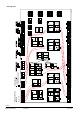
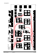
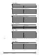
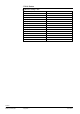
Plant type H0-7
a a a a d da
Q Q
x x
1
2
x x
3
4
0...1 0 V
Y Q
d
d
B
d
B
V
Q
2
)
1
)
3
P
R
1
Q
R
2
Q
d
d d
Q
Y Q
a a a a d da
Q
0...1 0 V
Y
Q
d
d
B
d
B
V
Q
2
)
1
)
3
P
a
R
1
Q
R
2
Q
d d
Q
a a a a d da
Q
0...1 0 V
Y Q
d
d
B
d
B
V
Q
2
)
1
)
3
P
a
R
1
Q
R
2
Q
d d
Q
RMH760
N .X5
x
N. X6
x
N.X4
x
N.X3
x
N.X2
x
N.X1
x
A7.X3
x
A7. X4
x
A7 .X2
x
A7.X1
x
RMZ789 (2)
A9.X6
x
A9 .X5
x
A9. X3
x
A9 .X4
x
A9 .X2
x
A9. X1
x
R
MZ78
9 (
1)
(
)
A2.X3
x
A2 .X2
x
A2.X1
x
A2.X3
x
A2 .X2
x
A2.X1
x
A 3.X3
x
A3.X4
x
A3. X2
x
A 3.X1
x
RMZ782 (2) RMZ783 RMZ787
A9 .X6
x
A9.X5
x
A9. X3
x
A9 .X4
x
A 9.X2
x
A9. X1
x
a d d d
Q
d d
B
d
B
V
Q
1
)
DC 0...1 0 V
a
0...1 0 V
Y
a
2
)
3
P
a d d d
Q
d d
B
d
B
V
Q
1
)
D C 0 ...10 V
a
0...1 0 V
Y
a
2
)
3
P
i i i i
1
2
3
4
1. 2.
da da ddd
Q Q Q
d
Q
d
B
d
B
V
Q
a
0...1 0 V
Y
0...1 0 V
Y
2
)
2
)
1
)
3
P
3
P
Y
d d d
a xa
Q
a
a d
0...1 0 V
Y
2
)
3
P
N.Y1
Y
N. Q4
Q
N. Q1
Q
N.Q2
Q
N.Q3
Q
N. Q5
Q
A9.Q2
Q
A9.Q3
Q
A9.Q4
Q
A9.Q1
Q
A7. Q1
Q
A
7.Q2
Q
A
7.Q3
Q Q
A7.Q5
N1 N2 N
1
N
2
N
3
N
4
N.Y2
Y
A9.Y1
Y
A9.Y2
Y
A9. Q2
Q
A9.Q3
Q
A9.Q4
Q
A9. Q1
Q
N
1
N
2
N
3
N
4
A9.Y1
Y
A9.Y2
Y
3
P
3
P
3
P
3
P
3
P
A2. Q2
Q
A2. Q3
Q
N
1
N
2
A2. Y1
Y
3
P
A2. Q2
Q
A2. Q3
Q
N
1
N
2
A2. Y1
Y
3
P
A3.Q2
Q
A3. Q3
Q
A3.Q5
Q
N
1
N
2
A3.Y1
Y
3
P
A3.Q4
Q
3
P
RMZ782 (1)
V
a a a
d
a a
d dd
Q
Y
3
P
Q QY
3
P
Q Q
V
d d
B
d
0...1 0 V
2
)
B
0...1 0 V
2
)
1
)
B
1
)
B
V
dd d
B
da
Q Q
B
0...1 0 V
Y
2
)
3
P
Q
dd
1
)
a
A2.Q1
Q
A2.Q1
Q
A3. Q1
Q
1 2 21
x x x x
A B
3
x
Q
d
C
1 2 21
x x x x
A
B
3
x
Q
d
C
1 2 21
x x x x
A B
3
x
Q
d
C
1 2 21
x x x x
A
B
3
x
Q
d
C
Q
a
a
d
A - B
Q
a a
d
A - B
x x xxx x x
...
...
X
1
2
3
4
X X X
.
Flow
Return
Room
Room rel.
Timer
Room abs.
Operating mode
clo se
open
Relay 1
Relay 2
He
ati
ng c
irc
uit
1
HC-
pum
p
Fault button
Heating limit
Heating
He
at
dema
nd
Operating mode
Outside
Flow
Return
Room
Room rel.
Room abs.
Operating mode
Timer
open
clo se
H
C-
pump
Heating limit
Operating mode
Flow
Return
Room
Room rel.
Room abs.
Outside
Operating mode
Timer
clo se
open
Heating limit
Operating mode
H
C-
pum
p
He
ati
ng c
irc
uit
3
He
ati
ng c
irc
uit
2
Heat requis.
Fr o st
Flow
Return
clo se
open
Main
pump
Disp la y 1
Disp la y 8
Win d
Solar
Outside
Legionella
function relay
P rimary
Flo w
Return
Flo w
Secondary
Con-
sumer
Circ u-
lation
Tank
Operating mode
clo se
open
clo se
open
clo se
open
Main
tai
n.
temp.
Flue gas
R
e
le
a
s
e
Flue gas m ode
.
Burner
Boiler
Return
Burner
Shutoff valve
Bo
ile
rp.
Bypassp.
(Water shortage) 1
(Overpressure) 2
(Underpressure) 3
Pump
fu
nct
:
Bo
ile
r
Mod
ul at
i ng
Sta
ge
clo se
open
Setpoint comp.
clo se
open
MBRT
Flow
Return
Heating
Fr o st
Primar y controller
H
e
a
t
r
e
q
u
i
s
.
System
pum
p
clo se
open
top
bottom
Flo w
Forced charging
4 Extension modules
1)
6 S
ingle o
r twin
pumps
2)
6 Cont
rol ou
tputs (
DC 0..
.10 V o
r 3-po
sitioni
ng)
3-
Posi tio
ning o
utput i
n pair
s Q1/Q2
, Q3/Q
4
Configuration Diagram
R
MH760B
Maximum
configuratio
n:
Plant type
Mis cellane ous
Main c ontr oller
F
aul
ts
Co
unter
D
HW
Primary
Return
Flow signal
Flow
clo se
open
Secondary
= from
= to
3133W01_H_en_a
Comparator 2
Comp
arator
1
Logi c
1
Logi k 2
Lo
gi k
3
L
ogi
k 4
Tr
end
H0-7