
Basic Documentation

239/256
Siemens Modular Heating Controller RMH760B CE1P3133en
Building Technologies 17 Appendix 2017-09-29
17 Appendix
17.1 Configuration diagrams
The use of the configuration diagrams is explained in subsection 3.2.4.
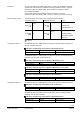
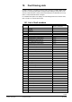
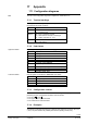
17.1.1 Terminal markings
The designations of the signal inputs and outputs and of the assigned connection
terminals are structured as follows:
Example
Explanation
N.X3
N = controller RMH760B
X3 = universal input
A9(2).Y1 A9 = type of extension module
(2) = 2nd extension module of same type
Y1 = analog output DC 0…10 V
N.Q5
N = controller RMH760B
Q5 = relay output
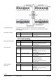
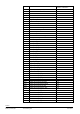
17.1.2 Code letters
Physical inputs and outputs are identified by uppercase code letters:
Code letter
Explanation
N
Heating controller RMH760B
A2
Heating circuit module RMZ782B
A3
DHW module RMZ783B
A7
Universal module RMZ787
A9
Universal module RMZ789
X Universal input
Q…
Switching load (changeover or NO contact)
Y
Analog output DC 0…10 V
3P
3-position output, pairs
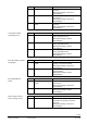
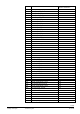
Internal signals are identified by lowercase code letters:
Code letter
Explanation
x
Analog or digital
a
Analog
d
Digital
i
Pulse
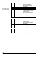
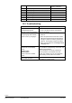
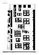
17.1.3 Configuration choices
Available are a maximum of 4 extension modules, 6 single or twin pumps, and 6
positioning outputs. Configuration is always made as follows:
• From arrow
to line
• From uppercase to uppercase letter
• From lowercase to lowercase letter
17.1.4 Examples
The following examples show the type of plant of each plant type group (H0, H0-x, H1-
x, H2-x, etc.) that contains all possible plant sections (heating circuits, etc.).
Use
Uppercase letters
Lowercase letters