
Basic Documentation

22/256
Siemens Modular Heating Controller RMH760B CE1P3133en
Building Technologies 3 Commissioning 2017-09-29
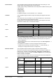
Plant type
Description
Plant diagram
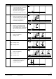
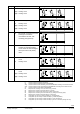
H2-1
N1:
A3:
Primary controller
DHW circuit with controlled mixing
valve in the storage tank flow and
charging pump (DHW 2)
A3
3133S17
N1
N.X1
N.Q3
N.Q1/Q2
H2-1
A3.X2
A3.Q1/Q2
A3.Q5
A3.X1
H2-2
N1:
A2:
Primary controller
Weather-compensated heating
circuit control with mixing valve
and circulating pump
A2
3133S18
N1
N.X1
N.Q3
N.Q1/Q2
H2-2
A2.X1
A2.Q3
A2.Q1/Q2
N.X2
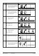
H2-3
N1:
A3:
A2:
Primary controller
DHW circuit (DHW 2)
Heating circuit
A2A3
3133S19
N1
N.X1
N.Q3
N.Q1/Q2
H2-3
A3.X2
A3.Q1/Q2
A3.Q5
A3.X1
A2.X1
A2.Q3
A2.Q1/Q2
N.X2
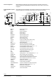
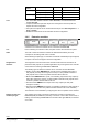
H2-4
N1:
A2(1):
A2(2):
Primary controller
Heating circuit
Heating circuit
A2(2)A2(1)
3133S20
N1
N.X1
N.Q3
N.Q1/Q2
H2-4
A2.X1
A2.Q3
A2.Q1/Q2
N.X2
A2.X1
A2.Q3
A2.Q1/Q2
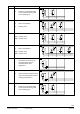
H2-5
N1:
A3:
A2(1):
A2(2):
Primary controller
DHW circuit (DHW 2)
Heating circuit
Heating circuit
A2(1)A3
A2(2)
3133S21
N1
N.X1
N.Q3
N.Q1/Q2
H2-5
A3.X2
A3.Q1/Q2
A3.Q5
A3.X1
A2.X1
A2.Q3
A2.Q1/Q2
N.X2
A2.X1
A2.Q3
A2.Q1/Q2
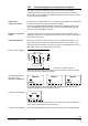
H3-0
N1: Boiler temperature control with 1-
stage burner and boiler pump
H3-0
N1
3133S23
N.X1
N.Q3
N.X3
N.Q5
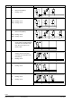
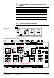
H3-1
N1:
A3:
Boiler temperature control
DHW circuit with controlled mixing
valve in the storage tank flow and
charging pump (DHW 2)
H3-1
A3N1
3133S24
A3.X2
A3.Q1/Q2
A3.Q5
A3.X1
N.X1
N.Q3
N.X3
N.Q5