
Basic Documentation

21/256
Siemens Modular Heating Controller RMH760B CE1P3133en
Building Technologies 3 Commissioning 2017-09-29
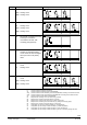
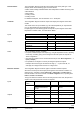
Plant type
Description
Plant diagram
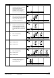
H1-0
N1: Main controller (district heat
connection with heat exchanger),
control of secondary flow
temperature with 2-port valve in
the primary return, supply to
internal and external consumers
3133S09
N1
N.X1
N.X3
N.Q1/Q2
H1-0
H1-1
N1:
A3:
Main controller
DHW circuit, storage tank charging
via heat exchanger with controlled
mixing valve, with primary and
secondary pump (DHW 4)
A3
3133S10
N1
H1-1
A3.Q1/Q2
A3.Q5
A3.X2
A3.X4
N.X1
N.X3
N.Q1/Q2
A3.Q3
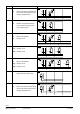
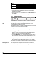
H1-2
N1:
A2:
Main controller
Weather-compensated heating
circuit control with mixing valve
and circulating pump, connected to
the secondary circuit of the main
flow
A2
3133S11
N1
N.X1
H1-2
A2.X1
A2.Q3
A2.Q1/Q2
N.X2
N.X3
N.Q1/Q2
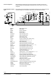
H1-3
N1:
A3:
A2:
Main controller
DHW circuit (DHW 4)
Heating circuit
A2A3
3133S12
N1
H1-3
A3.Q1/Q2
A3.Q5
A3.X2
A3.X4
A2.X1
A2.Q3
A2.Q1/Q2
N.X2
N.X1
N.X3
N.Q1/Q2
A3.Q3
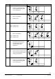
H1-4
N1:
A2(1):
A2(2):
Main controller
Heating circuit
Heating circuit
A2(2)A2(1)
3133S13
N1
H1-4
A2.X1
A2.Q3
A2.Q1/Q2
N.X2
A2.X1
A2.Q3
A2.Q1/Q2
N.Q1/Q2
N.X1
N.X3
H1-5
N1:
A3:
A2(1):
A2(2):
Main controller
DHW circuit (DHW 4)
Heating circuit
Heating circuit
A2(1)A3 A2(2)
3133S14
N1
H1-5
A3.Q1/Q2
A3.Q5
A3.X2
A3.X4
A2.X1
A2.Q3
A2.Q1/Q2
N.X2
A2.X1
A2.Q3
A2.Q1/Q2
N.X1
N.X3
N.Q1/Q2
A3.Q3
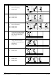
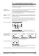
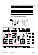
H2-0
N1: Demand-compensated primary
controller with mixing valve and
circulating pump, supply to
external consumers
3133S16
N1
N.X1
N.Q3
N.Q1/Q2
H2-0