
Basic Documentation

182/256
Siemens Modular Heating Controller RMH760B CE1P3133en
Building Technologies 11 Logic functions 2017-09-29
11 Logic functions
11.1 Logic
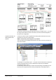
Use the Logic block for logical links to multiple input signals.
4 independent Logic function blocks are available.
One operation selector
can be activated for each Logic block, allowing users to
manipulate the program from the highest main menu level.
Auto, Off or On can be selected. Manipulation acts on the output of the Logic function
block.
You can set a switch-on and switch-off delay as well as minimum switch-on and switch-
off periods for the output signal on function block C.
These time always work (e.g. for an operation selector
manipulation), except
during a wiring test.
You can assign a digital or analog signal to each input.
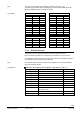
You can generate an analog signal, a 2-point signal (On/Off) via switch on and off
points. The following applies:
Switching value On > switching value Off: Transition 0 1
Switching value On < switching value Off: Transition 1 0
The difference between switching value On and switching value Off is the hysteresis.
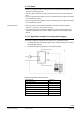
• Inputs 1, 2 and 3 are internally connected to Logic A
• Inputs 1 and 2 are connected to Logic B
• The logical functions AND, NAND, OR, NOR can be set for Logic A and Logic B
• The results from Logics A and B act on Logic C
• In Logic C, you can select logic functions AND, NAND, OR, NOR , EXOR, EXNOR
d
1 2 21
x x x
x
3
x
Q
A
B
C
Logic Logic
Logic
3123Z03en
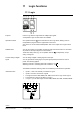
Purpose
Operation selector
Settable times
Convert analog to digital
signal
Internal structure