
Basic Documentation

109/256
Siemens Modular Heating Controller RMH760B CE1P3133en
Building Technologies 9 Heating circuit control 2017-09-29
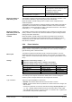
9 Heating circuit control
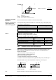
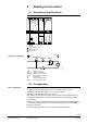
9.1 Overview of function block
a a a a d da
Q
0...10 V
Y
Q
d d
B
d
B
V
Q
2)
1)
3P
a
R1
Q
R2
Q
d d
Q
Flow
Return
Room
Room rel.
Room abs.
Outside
Operating mode
Timer
close
open
Heating limit
Operating mode
HC-
pump
Heating circuit 3
Timer function
Special day input
Holiday input
3133S101
T
T
TRtHCtr
TFlHCtr
HCtrPu
HCtrVlvMx
T
TR
HCtrPu_B
T
TO
HctrPu
Heating circuit pump
HctrPu_B
Heating circuit pump B
HCtrVlvMx
Heating circuit mixing valve
TFlHCtr
Flow temperature sensor
TO
Outside sensor
TR
Room temperature sensor
TRtHCtr
Return temperature sensor
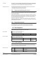
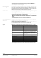
9.2 Configuration
With the following plant types, the heating circuits are activated per default:
• Heating circuit 1 with plant types Hx-2, Hx-3, Hx-4, Hx-5, Hx-6, and Hx-7
• Heating circuit 2 with plant types Hx-4, Hx-5, Hx-6, and Hx-7
• Heating circuit 3 with plant types Hx-6, and Hx-7
Each heating circuit always has a mixing valve, pump and flow temperature sensor
preconfigured. Plant types H5-x and H6-x also have the return temperature sensor
preconfigured.
Heating circuit 1 is preconfigured based on the basic module or the RMZ782B heating
circuit module. Heating circuits 2 and 3 are always preconfigured on the RMZ782B
heating circuit module.
For more detailed information, refer to section 3.2 "Basic configuration".
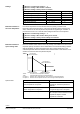
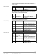
Heating circuit diagram
Basic configuration