s Synco TM 700 Modular Heating Controller RMH760B Including extension modules RMZ782B, RMZ783B, RMZ787 and RMZ789 Basic Documentation CE1P3133en 2017-09-29 Building Technologies
Contents 1 Summary.......................................................................................................10 1.1 Product range .................................................................................................................... 10 1.2 System topology ................................................................................................................ 11 1.3 Equipment combinations ................................................................................
4.4 Contrast of display ............................................................................................................. 40 4.5 Text entries ........................................................................................................................ 41 4.5.1 Device name and file name ............................................................................................... 41 4.5.2 Function block ...........................................................................
6.5.3 Control of burner’s basic stage and stage 2 ....................................................................... 71 6.5.4 Control of modulating burners ............................................................................................ 73 6.5.5 External boiler temperature control .................................................................................... 77 6.6 Protective boiler functions ......................................................................................
8.7 Setpoint increase ............................................................................................................. 101 8.8 Limit and protective functions........................................................................................... 102 8.8.1 Frost protection................................................................................................................ 102 8.8.2 Limitations ..................................................................................
9.8.2 Limitation of the return temperature ................................................................................. 134 9.8.3 Minimum limitation of the return temperature ................................................................... 135 9.8.4 Frost functions and general protective functions .............................................................. 135 9.8.5 Pulse limitation.............................................................................................................
10.7.2 Load control ..................................................................................................................... 169 10.8 Limitation and protective functions ................................................................................... 170 10.8.1 DHW discharging protection ............................................................................................ 170 10.8.2 Limitation of the return temperature ...........................................................
11.2.10 Troubleshooting ............................................................................................................... 194 11.2.11 Application example solar DHW ....................................................................................... 194 12 Function block meter.................................................................................197 12.1 Overview of function block ...............................................................................................
15 Communication ......................................................................................... 218 15.1 Basic settings .................................................................................................................. 218 15.2 Calendar data (holidays and special days)....................................................................... 219 15.3 Room data ......................................................................................................................
1 Summary 1.1 Product range Room unit Name Type Data Sheet Switching and control unit Heating controller RMH760B N3133 Extension modules Heating circuit module DHW module Universal modules RMZ782B RMZ783B RMZ785 RMZ787 N3136 Module connector RMZ780 N3138 Operator unit, plug-in type RMZ790 N3111 Operator unit, detached RMZ791 N3112 KNX Bus operator unit RMZ792 N3113 Room unit QAW740 N1633 Service tool OCI700.
1.2 System topology Web-Browser Internet Router Ethernet OZW772... RDG.. RX.. RDF/RDU RMZ792 RMZ790 RMZ791 RMS.. RMB.. RMK.. RMU.. OCI700.1 RMZ78.. OCI702 Key RMB.. RMH.. RMK.. RMS.. RMU.. RMZ78.. OZW772.. Central control unit Heating controller Boiler sequence controller Switching and monitoring device Universal controller Extension modules Web server RMZ790 RMZ791 RMZ792 RDG.. RDF.. RDU.. RX.. OCI700.
1.4 Product documentation In addition to this Basic Documentation, the product documents listed below provide detailed information about the safe and correct deployment and operation of Synco™ 700 products in building services plant. The documents can be downloaded from http://siemens.com/bt/download. Type of document Document no.
1.5 Important notes This symbol shall draw your attention to special safety notes and warnings. If such notes are not observed, personal injury and / or considerable damage to property can occur. Field of use Synco™ 700 products may only be used for the control and supervision of heating, ventilation, air conditioning and chilled water plant. Correct use Prerequisites for flawless and safe operation of Synco™ 700 products are correct transport, installation, commissioning, and operation.
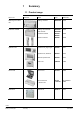
2 Operation Synco™ 700 devices may only be operated by staff who has been instructed by SBT HVAC Products or their delegates and whose attention has been drawn to potential risks. 2.
2.2 Operation with operator unit 2.2.1 Functions of the operator unit The operator unit is used to make all settings and readouts required for operating the controller. All entries made on the operator unit are transmitted to the controller where they are handled and stored; the operator unit itself does not store any data. Information for the user is generated by the controller and forwarded to the operator unit where it is displayed. 2.2.
Display examples Start display: Wednesday 15.11.2006 Welcome Information 14:52 Main menu: Setting level. Selection of a setting parameter, e.g. on the "Main menu" of the user level: Main menu: Time switch Room operating mode Controller 1 Controller 2 Setting level, pop-up, setting a numerical value: Entry 1 Start ––.––.–– 25.02 End ––.––.–– Reason Delete entry ––.–– ––.–– Holidays Setting level, Help picture "Explanations relating to the selected datapoint".
Switching between the operating levels • Switching from the info level to the setting level: 1. Select the start page by pressing the ESC button. 2. Press the OK knob to change to the setting level. • Switching from the setting level to the info level: 1. Select the start page with the ESC button. Press the button repeatedly until the start page reappears. 2. Press the INFO button to change to the info level. 2.2.4 Access rights An access right is defined for each parameter (operating line).
3 Commissioning Preparations for using and commissioning the Synco™ 700 controllers must be made by qualified staff who have been appropriately trained by SBT HVAC Products. 3.1 Entering the commissioning mode During commissioning, both control and the plant’s safety functions remain deactivated! The relays are deenergized, which means that their normally open contacts are open. When supplying power to the controller for the first time, the Language menu appears.
3.2.1 Selecting the plant type Setting The first setting to be made is always the plant type because when selecting the type of plant, the majority of settings are reset to their default values. Following will not be reset: • Texts • Business card • Device name • Terminal types • Time switch • Holiday program Plant types The RMH760B contains 41 plant types. If required, every type of plant can subsequently be changed or complemented via "Extra configuration".
Plant types Plant type Description H0-1 Basic type N1: DHW circuit with controlled mixing valve in the storage tank flow and charging pump, connected directly to uncontrolled main flow (DHW type DHW 2) H0-1 3133S01 H Plant diagram No preconfigured inputs and outputs N.X2 N.X1 N.Q4 N.Q1/Q2 H0-2 N1: Weather-compensated heating circuit control with mixing valve and circulating pump, connected directly to uncontrolled main flow H0-2 3133S02 N1 N.X2 N.X1 N.Q3 N.
Plant type Description N1: Main controller (district heat connection with heat exchanger), control of secondary flow temperature with 2-port valve in the primary return, supply to internal and external consumers H1-0 3133S09 H1-0 Plant diagram N.X1 N.X3 N.Q1/Q2 N1 Main controller A3: DHW circuit, storage tank charging via heat exchanger with controlled mixing valve, with primary and secondary pump (DHW 4) H1-1 A3.X4 A3.X2 A3.Q5 A3.Q3 N.X1 A3.Q1/Q2 N.X3 N.
Plant type Description N1: Primary controller A3: DHW circuit with controlled mixing valve in the storage tank flow and charging pump (DHW 2) H2-1 3133S17 H2-1 Plant diagram N.X1 N.Q3 A3.X2 A3.X1 A3.Q5 N.Q1/Q2 A3.Q1/Q2 A3 H2-2 N1: Primary controller A2: Weather-compensated heating circuit control with mixing valve and circulating pump H2-2 3133S18 N1 N.X2 N.X1 A2.X1 N.Q3 A2.Q3 A2.Q1/Q2 N.
Plant type Description N1: A2: Boiler temperature control Weather-compensated heating circuit control with mixing valve and circulating pump H3-2 3133S25 H3-2 Plant diagram N.X2 A2.X1 N.X1 A2.Q3 N.Q3 A2.Q1/Q2 N.X3 N.Q5 N1 N1: Boiler temperature control A3: DHW circuit (DHW 2) A2: Heating circuit H3-3 3133S26 H3-3 A2 N.X2 N.X1 A3.X2 A3.X1 A2.Q3 A3.Q5 N.Q3 N.X3 N.Q5 A2.Q1/Q2 A3.
Plant type Description N1: Boiler temperature control A3: DHW circuit (DHW 2) A2: Heating circuit H4-3 3133S33 H4-3 Plant diagram N.X2 N.X1 A2.Q3 A3.Q5 N.Q3 N.X3 A2.X1 A3.X2 A3.X1 A2.Q1/Q2 A3.Q1/Q2 N.Q5 N.Q1/Q2 H4-4 N1: Boiler temperature control H4-4 A2(1): Heating circuit N.X1 A2(2): Heating circuit N.Q3 A3 A2 3133S34 N1 N.X2 A2.X1 A2.X1 A2.Q3 A2.Q3 A2.Q1/Q2 A2.Q1/Q2 N.X3 N.Q5 N.
Plant type Description Heating circuit H5-6 N.X2 A2(1): Heating circuit N.X1 A2.X1 A2.X1 N.Q3 A2.Q3 A2.Q3 A2(2): Heating circuit N.X3 A3: DHW circuit (DHW 3) N1: Heating circuit A2.Q1/Q2 A2.Q1/Q2 A2(1) N1 H5-7 A2.X3 A2.X3 N.Q1/Q2 A2(2) H5-7 N.X2 A3.X4 A3.X2 A2(1): Heating circuit 3133S42 N1: 3133S41 H5-6 Plant diagram N.X1 A2.X1 A2.X1 N.Q3 A2.Q3 A2.Q3 N.X3 A3.Q3 A3.Q1/Q2 A2.X3 N.Q1/Q2 A2.X3 A2.Q1/Q2 A2.
When selecting the plant type, the sensors required for the basic functions and standard outputs will automatically be predefined and, for this reason, need not be configured. Preconfiguration of plant types Every plant type has several plant components preconfigured. The following summary shows the assignment of the plant components to the connection terminals.
3.2.2 Terminal assignment and properties of outputs In principle, all input and output terminals can be freely used. The terminals preassigned when selecting the plant type can also be reconfigured. In that case, however, the special properties of the individual extension modules, and their outputs, must be taken into consideration. Outputs with changeover contacts For the control of a shutoff valve, an on / off signal is usually required.
3.2.
Function blocks The configuration diagram shows all function blocks active in the plant type. In this example, these are the following types of function blocks: • Boiler control including maintained boiler return temperature controlled via mixing valve • Miscellaneous • DHW heating • Heating circuit 1 • Heating circuit 2 For additional examples, refer to subsection 17.1.4 "Examples". Controller The configuration diagram shows the inputs and outputs preconfigured in the basic module.
Type of module RMZ782B(1) RMZ782B(2) Terminal Designation in diagram 3-position mixing valve Heating circuit pump 3-position mixing valve Heating circuit pump Q1 and Q2 Q3 Q1 and Q2 Q3 A2.Q1/Q2 A2.Q3 A2.Q1/Q2 A2.Q3 • "A2." in the table denotes extension module RMZ782B, "A3" denotes extension module RMZ783B.
3.2.6 Basic configuration Configuration of the controller is always started by defining the plant type.
Fault handling Fault status messages If the extension modules actually used and their positions do not accord with the values entered, a fault status message Fault extension module will be delivered. In the case of an incorrectly configured extension module, some other fault status message may also be displayed because that consequential fault has the higher priority than fault status message 7101. It is therefore of advantage to have all pending faults displayed.
Maximum plant size The maximum plant size is limited by the number of available terminals and the number of plant elements (pumps and actuators or positioning outputs): Plant element Maximum number Pumps 6 Positioning outputs 6 Following applies: • A twin pump is regarded as one pump • A positioning output is used for an actuator or a modulating burner. If both the modulating output and the 3-position positioning output are configured, the 2 are regarded as one positioning output 3.3.
Setting Main menu > Commissioning > Settings > … or Main menu > Settings > Inputs > …X… Operating line Range Factory setting Value low Depending on the selected type Depending on the selected type Depending on the type Depending on the type Value high Example Flow temperature with an active signal of DC 0…10 V = 0…100 °C: Lower limit value: 0 °C Upper limit value: 100 °C Measured value correction With passive temperature sensors, the measured value can be readjusted by −3.0…+3.
3140A05 G F... AC 24 V F... ∆p G X... M X... M G0 N G0 Fault handling Digital signals cannot be monitored. 3.4 Wiring test A wiring test can be made with all connected peripheral devices. We recommend to conduct this test after the configuration and the settings have been made. Inputs The current states are indicated at the inputs. Outputs The aggregates connected to the outputs (pumps, actuators, etc. ) or messages (e.g. for conventional controllers) can be switched on and off.
3.5 Completing commissioning If the application is valid, the Commissioning menu can be quit as follows: 1. Press the ESC button. The display shows a menu with the following information: Caution! Plant starts ESC 2. OK Confirm by pressing the OK knob. Then, the controller starts with the settings made; the plant is started up, and the Main menu appears on the display. Main menu: Commissioning Heating circuit 1 Heating circuit 2 Heating circuit 2 3.
3.7 Device information The Device information menu provides information about the controller, shows the software version, etc. Display values Main menu > Device information > Controller Operating line Adjustable values / display / remarks Plant type Plant type adapted Display of plant type Display of intervention in the programmed application (yes, no) Has a function only in connection with ACS7… Display of file name of the application currently loaded. Can be edited under Settings > Texts > File name.
4 General settings 4.1 Time of day and date 4.1.1 Operating principle The controller has a yearly clock with time of day, weekday and date. Time format Setting The following time formats are available: Time Date Example format 24 hours dd.mm.yyyy 31.05.2006 (day.month.
Setting values Main menu > Commissioning > Communication > Basic settings Operating line Clock time operation Remote setting clock slave Range Autonomous / slave / master Yes / No Factory setting Autonomous Yes If the controller is set as a clock time slave, it can also be selected whether it shall be possible to adjust the master clock’s time of day from this controller.
4.2 Selecting the language Every RMH760B controller has a number of languages loaded. When switching on the controller for the first time, the required language must be entered. But the language can also be changed later during operation. The following languages are loaded: English, German, French, Italian, Spanish, Portuguese, Dutch, Danish, Finnish, Norwegian, Swedish, Polish, Czech, Hungarian, Russian ,Slovakian, Bulgarian, Greek, Romanian, Slovenian, Serbian, Croatian, Turkish.
4.5 Text entries 4.5.1 Device name and file name The text for the device name appears in the welcome picture. Setting Main menu > Commissioning > Settings > … or Main menu > Settings > Texts Operating line Device name File name Range Max. 20 characters Max. 20 characters Factory setting Device name The text of the device name entered here appears on the start page in place of Welcome.
4.5.4 Electronic business card The text of the electronic business card is displayed as an info picture. The electronic business card can be deactivated via "Extra configuration".
5 General functions, fundamentals 5.1 Time switch For each of the 3 heating circuits, DHW heating and the DHW circulating pump, there is a time switch available. In "Automatic" mode, the respective function block operates according to this time switch. A switching program can be defined for every weekday. Using the program entered, the time switch controls the change of operating modes and the relevant setpoints. Operation of the time switch is described in Operating Instructions B3133. 5.1.
Main menu > Commissioning > Communication > Heating circuit 1 (or 2 or 3) Operating line Geographical zone (apartm.) Time switch slave (apartm.) Range ---- / 1…126 ---- / 1…126 Factory setting ------- Main menu > Commissioning > Communication > DHW Operating line DHW zone Time switch operation Time switch slave DHW Range 1…31 Autonomous / Slave / Master 1…31 Factory setting 1 Autonomous 1 For details on settings regarding time switch communication, refer to chapter 15 "Communication". 5.1.
Circulating pump Entries For the circulating pump, a specific 24-hour program can be selected for each day: Main menu > DHW > Circ pump time switch Operating line Monday Range Off / On Factory setting From 05:00 On From 22:00 Off up to Sunday Off / On Special day Off / On From 05:00 On From 22:00 Off From 05:00 On From 22:00 Off The special day program is a 24-hour program which can be activated either via the holiday program or an external contact.
5.1.3 >1 time switch signal in the heating circuit Fault handling Number Text Effect 5102 >1 time switch in heating circuit 1 >1 time switch in heating circuit 2 >1 time switch in heating circuit 3 >1 DHW time switch Nonurgent message; must be acknowledged Nonurgent message; must be acknowledged Nonurgent message; must be acknowledged Nonurgent message; must be acknowledged 5112 5122 5302 For each geographical zone, only one time switch master may be set.
The following combinations are possible: Effect Autonomous The holidays / special day program only acts in its own heating circuit or DHW and only in the controller. The holidays / special day program has no impact on the holidays / special day zone entered on the "Communication" menu. The holidays / special day program of this heating circuit or of DHW is not active; a holidays / special day program selected on the slave will be ignored.
Circulating pump For the circulating pump, following applies during the holiday period: • If "Protection" has been selected as the DHW operating mode during the holiday period, the circulating pump will be deactivated • In the other operating modes, the circulating pump will run according to the time program Legionella function For the legionella function, following applies during the holiday period: • If "Protection" has been selected as the DHW operating mode during the holiday period, the legionella f
Note On completion of the holiday period or the special day, operation according to the normal 7-day program will be resumed. During this transition period, it can occur that optimum start control (e.g. boost heating) cannot be started in due time. It is therefore recommended to bring the end of the holiday period somewhat forward, giving the plant sufficient time to adapt to the respective setpoints. 5.2.
Fault status messages Number Text Effect 5201 Hol/sp day prgm failure HC 1 Nonurgent message; must not be acknowledged 5211 Hol/sp day prgm failure HC 2 Nonurgent message; must not be acknowledged 5221 Hol/sp day prgm failure HC 3 Nonurgent message; must not be acknowledged 5231 Hol/sp day prgm failure DHW Nonurgent message; must not be acknowledged 5202 >1 hol/sp day prgm HC 1 Nonurgent message; must be acknowledged 5212 >1 hol/sp day prgm HC 2 Nonurgent message; must be acknowledged
Main menu > Settings > Boiler > Limitations Operating line Frost prot boiler pump Range Off / On Factory setting Off The necessity for activating "Frost protection for the plant" is primarily dependent on the type of hydraulic system and the location of the heating pipes in the building. If the heating pipes are located such that they cannot be affected by frost, frost protection for the plant will not be required.
This setting can only be made on plant with no boiler. Every heat consumer has a minimum overrun time of 60 seconds. With DHW heating, it is to be noted that discharging protection is given priority over pump overrun. In the case of DHW heating with primary and secondary pump, the secondary pump operates for an additional pump overrun time to prevent the external heat exchanger from reaching excessive temperatures.
5.6 Heat demand and load control 5.6.1 Heat demand Heat consumers, such as heating circuits and DHW heating, send their heat demand signals to the heat distribution zone "Heat generation". A demand transformer converts such signals to appropriate heat demand signals (for details, refer to section 7.3 "Heat demand transformer". Heat source or primary controller receive the heat demand signals and evaluate them.
5.6.2 Load control Load control enables heat generation to reduce the amount of heat drawn by the heat consumers (load reduction via locking signals), or to increase it (load increase via forced signals). In the case of load control via locking signals, a differentiation is made between critical and uncritical locking signals. In the case of forced signals also, a distinction is made between critical and uncritical signals.
For the main controller and the primary controller, setting "Response to uncritical locking signals" is not required. Both never respond to uncritical locking signals because the associated hydraulic actuating devices shall be able to respond depending on the situation. This locking signal gain is adjustable between 0 and 200 %.
5.7.2 With the help of the P-band (Xp) and the integral action time (Tn), the mixing valve algorithm can be optimally adapted to the relevant controlled system. The controller is supplied with the control parameters set to values suited for the majority of controlled systems (typically flow temperature control with a 3-port mixing valve). In the case of difficult controlled systems (e.g. heating circuit with heat exchanger), the control parameters must always be matched to the type of controlled system.
Example Change of valve position ∆y = 40 % Change of flow temperature ∆x = 18 K Tu = 6 s Tg = 18 s P-band: Xp = 2 × 6 s / 18 s × 18 K / 40 % × 100 % = 30 K Integral action time: Tn = 3 × 6 s = 18 s To get a reliable step response, it is important to keep the temperature upstream of the valve and the return temperature (mixing) as constant as possible during the time the measurement is made.
Actuator running time The actuator running time must be matched to the type of actuator used. This setting is important for both 3-position and DC 0…10 V actuators. If in doubt with 3-position actuators, the setting is to be increased since otherwise the actuator will not optimally operate in the range between 0 and 100 % stroke (also refer to synchronization pulse in subsection 5.7.3). Note It is important to also set the actuator running time with DC 0…10 V actuators.
5.8 Pump control and twin pumps Every pump (main pump, boiler pump, system pump, heating circuit pump) can be monitored with a flow switch and an associated fault input. Also, every pump can be a twin pump. d d d B V B Q Q 3133Z15 1) The decision whether the pump to be installed shall be a single or twin pump is made via "Extra configuration" at the respective function block (heating circuit, DHW, primary controller, main controller, boiler).
Main menu > Settings > Boiler > Twin pump Operating line Run priority Changeover period 5.8.1 Range Auto / Twin pump A / Twin pump B –60…0…+60 s Factory setting Auto 0s Changeover logic Run priority For pump changeover, there are 3 choices available: • Automatic changeover once a week; should the working pump become faulty, changeover to the second pump will take place.
The change from pump A to pump B is made after a certain pause, e.g.
6 Boiler temperature control 6.1 Overview of function block B V Pump funct: Boilerp. Bypassp. d d d d (Water shortage) 1 (Overpressure) 2 (Underpressure) 3 d d d Shutoff valve d a d B urn er F lue g as F lue g as m ode . Release B urn er Boiler Return a a d d Y Q Q Block diagram Q 3P Y 3133Z09 Y B 3133W11 3P 2) 1) 0...10 V Q Q 0...10 V 1. 2. open close 2) MBRT open close Stage Modulating Setpoint comp.
TFg T BuSt1 BuSt2 BuMdlt BoSetpt P PMaxMon(Er2) WLoLeDet(Er1) T TBo 3133S100 Boiler diagram BuFb ErBu T TRtBo V BoPu BoPu_B BoPuErFlow BoPuEr BoPuEr_B P PMinMon(Er3) VlvShOffFb VlvShOff VlvRtMx BoPu BoPu_B BoPuEr BoPuEr_B BoPuErFlow BoSetpt BuFb BuMdlt BuSt1 BuSt2 WLoLeDet (Er1) PMaxMon (Er2) PMinMon (Er3) ErBu TBo TFg TRtBo VlvRtMx VlvShOff VlvShOffFb Boiler pump Boiler pump B Fault input boiler pump Fault input boiler pump B Flow supervision boiler pump Boiler temperature setpoint DC 0…10
Inputs Main menu > Commissioning > Extra configuration > Boiler > Inputs Operating line Boiler sensor Return sensor Release input Checkback signal burner Fault burner Flue gas temperature sensor Flue gas meas mode contact [Boiler pump] overload [Boiler pump B] overload Flow signal pump Checkb sign shutoff valve Fault input 1 Fault input 2 Fault input 3 Outputs Adjustable values / display / remarks Main menu > Commissioning > Extra configuration > Boiler > Outputs Operating line Burner stage 1 Burner sta
Checkback signal shutoff valve Flue gas temperature sensor If no checkback signal is received, an appropriate fault status message will be delivered. In addition, the burner will be started only if the shutoff valve's checkback signal indicates a fully open valve. If no checkback signal is received, an appropriate fault status message will be delivered. For more detailed information, refer to section 6.9. Using the flue gas temperature sensor, the flue gas temperature can be displayed and monitored.
TBo BoPu TRtBo ByPu 3133S72 TBo Plant types H3-x Boiler hydraulics 3133S71 6.2.2 TRtBo Boiler pump in the flow TBo Boiler temperature sensor TRtBo Return temperature sensor (optional, for minimum limitation) BoPu Boiler pump ByPu Bypass pump Boiler pump in the bypass For plant types with boiler (H3-x and H4-x), a boiler pump is always configured. This boiler pump can also be operated parallel to the boiler, or it can be configured as a boiler bypass pump.
In most cases, the boiler can be hydraulically decoupled via a shutoff valve. In the case of plant with a mixing valve for minimum limitation for the return temperature, this function is performed by the mixing valve. If the boiler is not released, the mixing valve is driven to the fully closed position so that the boiler will be hydraulically decoupled from the plant. Shutoff valve Shutoff valve for hydraulically decoupling the boiler from the system.
Control of the shutoff valve Normally, the shutoff valve is fully open when the boiler is released. In the case of the maintained boiler return temperature where the boiler is always kept at the minimum temperature, the behavior of the shutoff valve can be parameterized. When Open is selected for the shutoff valve (maintained boiler temperature), the valve will always be opened when the burner runs, even if there is no heat request. Depending on the type of hydraulic system, this may not be required (e.g.
6.4 Releasing and locking a boiler Manual switch A boiler can be released or locked either via the digital input (release input) or operation (boiler operating mode). Main menu > Commissioning > Settings > … or Main menu > Boiler > Boiler operating mode Operating line Range Factory setting Auto / Release DHW / Auto Off With the digital release input, the boiler will stay locked as long as the input is passive.
During test mode, fault status message Boiler test operation active is displayed. It is maintained until preselection "Test mode" is set back to "Auto". This is to make certain that the plant will not be quit without ending the test mode. Auto In the "Auto" position, the boiler is released and the test mode deactivated. Boiler off The boiler will be switched off, that is, the burner will be shut down and the pumps deactivated. Pump on (burner off) The boiler is released.
Minimum burner running time, burner cycling protection If the switch-off point is reached before the minimum burner running time has elapsed, the burner will continue to operate until that time is completed (burner cycling protection). The minimum burner running time is given priority. The burner’s switch-off point will be raised by half the boiler’s switching differential.
Burner stage 2 The release logic for 2-stage operation aims at ensuring an optimum switch-on time for stage 2 which, in addition to a time criterion, also considers the amount of heat deficit, calculated with a temperature-time integral. Time criterion As soon as the burner’s basic stage is switched on, the minimum locking time for burner stage 2 starts to run. This ensures that the burner will always operate with the basic stage for a certain minimum period of time.
Through the generation of the temperature-time integral it is not only the period of time that is considered, but also the extent of overshoot. This means that when the overshoot is significant, burner stage 2 will be locked earlier. When the reset integral (area "b" in the diagram) reaches the set value of the reset integral of stage 2 (point in time treset), stage 2 will be locked and the basic stage switched off. TBo TBoSrtpt + 1/2SDBo TBoSetpt - 1/2SDBo t BuSt1 1 0 t INT max. 0 max.
When the demand for heat is small, the basic stage cycles. When the demand for heat increases, the 3-position output or a DC 0…10 V output is used to control the combustion air damper. At the same time, the amount of fuel supplied will also be increased, typically via an additional switch on the air damper, or by simultaneous control of the amount of fuel (gas / air ratio). P M BV OH Q...
TBo Release integral modulation TBoSetpt + SDBo b TBoSetpt + ½ SDBo TBoSetpt 1K 1K TBoSetpt - ½ SDBo a a t StModulat. d c d d 3131D01 StBasic a b c d Release integral modulation (release integral stage 2 with 2-stage burner) Reset integral modulation (reset integral stage 2 with 2-stage burner) Neutral zone On / off pulses SDBo Boiler’s switching differential St Basic Burner’s basic stage St Modul.
Derivative action time (Tv) The derivative action time has an impact on the controller’s D-characteristic. If Tv = 0, the controller has PI characteristics. Setting rules for Xp, Tn and Tv The majority of plants change their behavior depending on the load. If the setting values are not adequately adjusted, the control system’s response is either too slow or too fast.
Control action is too fast If the control system’s response is too prompt so that significant overshoot or even permanent oscillations occur, setting parameters Xp, Tn and Tv must be increased in steps. A new readjustment should be made only after the control action resulting from the previous readjustment is completed. TBo 3132D11 TBoSetpt t 1. 2. 3. Reduce Xp in steps of about 25 % of the previous value. Increase Tv in steps of 2 to 5 seconds.
6.6.1 Maximum limitation of the boiler temperature This setting is used to provide maximum limitation of the boiler temperature setpoint. For control of the burner, this value represents the switch-off point. In this range, the boiler’s switching differential downward is calculated. Maximum limitation of the boiler temperature is always active. The only exception is the wiring test. TBo TBoMax 80 TBoSetpt 70 SDBo 60 40 30 0 3131D39 50 TBoMin 20 HD SDB0 TBo TBoMax TBoMin TBoSetpt 6.6.
3131D41 3131D40 TBoMin TBoMin Burner swich-on command Burner swich-on command Optimization of minimum boiler temperature On Optimization of minimum boiler temperature Off 6.6.4 Protection against boiler overtemperatures To protect the boiler against overtemperatures on burner shutdown because, possibly, none of the heat consumers draws heat, a consumer overrun time can be set.
6.6.8 Protective boiler startup To protect the boiler against condensation, a minimum boiler temperature is usually preset. This ensures that, in normal operation, the boiler temperature will not fall below a minimum level.
Summer When using the Summer setting, the boiler is not maintained at the minimum boiler temperature only when the boiler has identified summer operation. The change to summer operation takes place at midnight when, previously, the boiler has received no heat request from the heating circuits for 48 hours. A heat request from DHW heating will be accepted, however.
correctly acquired, it must be made certain that the maintained boiler return temperature will have no impact on DHW heating. Also, the maintained boiler return temperature must not act on the main pump if the return temperature is only correctly acquired when the main pump runs. In the case of a boiler with bypass pump (boiler pump parallel to the boiler), maintained boiler return temperature can be ensured by activating the bypass pump.
After the burner has been shut down, pump overrun (refer to section 5.4 "Pump overrun and mixing valve overrun") also acts on the bypass pump. In addition to activating the bypass pump, locking signals are generated if required and when a return temperature sensor is connected. If this is not required, setting "None" can be selected for "Lock sig maintained boil ret temp".
6.6.12 Protection against pressure shocks Main menu > Commissioning > Settings > … or Main menu > Settings > Boiler > Limitations Operating line Range Factory setting Delta boiler temp max (stage 2) 0…10 K 1K To prevent pressure shocks in the gas network when stages 1 and 2 are simultaneously switched off, stage 2 is switched off before the maximum boiler temperature is reached, the difference being "Delta boiler temp max (stage 2)".
When the actual flue gas temperature lies 5 K below the maximum value, the fault status message can be reset by making an acknowledgement. When resetting, the slave pointer value is also reset to the current value.
Main menu > Commissioning > Extra configuration > Boiler > Inputs Operating line Adjustable values / display / remarks Checkback signal burner Checkb sign shutoff valve Fault burner Fault input 1 Fault input 2 Fault input 3 [Boiler pump] overload [Boiler pump B] overload Flow signal pump The type of fault input can be parameterized at menu item …Settings > Inputs at the relevant terminal.
Main menu > Commissioning > Settings > … or Main menu > Settings > Boiler > Fault settings > Checkback signal burner Operating line Range Factory setting Signal delay start Signal interruption operation Impact of fault 00.05…59.55 m.s 00.00…59.55 m.s No stop / Stop 04.00 m.s 20.00 m.
6.10 Burner hours run counter and burner start counter For burner stage 1 or the burner’s basic stage, a checkback signal can be configured. In addition to burner supervision, this checkback signal is used for the burner hours run counter and the burner start counter. When there is no checkback signal, the burner hours run counter is started by the output relay for burner stage 1.
Faults of the boiler pump Number Text Effect 2331 Boiler overpressure 2341 Boiler underpressure 2351 2361 Shutoff valve no checkb signal Flue gas overtemperature Priority, effect and acknowledgement can be parameterized. Factory setting: "Urgent". Boiler stop, must be acknowledged Priority, effect and acknowledgement can be parameterized. Factory setting: "Urgent". Boiler stop, must be acknowledged Urgent message; must be acknowledged and reset.
Operating line Flow signal pump Fault burner Checkback signal burner Burner hours run Burner start counter Flue gas temperature Flue gas temperature maximum Flue gas temperature limit value Flue gas meas mode contact Fault text Fault input 1 Fault text Fault input 2 Fault text Fault input 3 Attenuated outside temp Outputs Adjustable values / display / remarks Fault text for fault input 1 Fault text for fault input 2 Fault text for fault input 3 Main menu > Boiler > Outputs Operating line Adjustable valu
7 Heat demand and heat requests 7.1 Heat requests The following sources can deliver heat requests to the controller: • The internal heating circuit • The internal DHW circuit • External controllers via the KNX bus • As a continuous DC 0…10 V signal • As a 2-position signal Heat requests can be delivered either via the main controller or the primary controller.
Heat request heating circuits KNX Heat request primary controller Primary controller + Main flow maximum setpoint Heat request DHW Heat request DC 0...
Both outputs are always available, even if no main controller has been configured. • If only a boiler is configured, the requests received will be forwarded to the boiler • If neither a boiler nor a main controller is configured, the requests received from the heat distribution zone will be forwarded For notes on configuration, refer to section 8.2 "Configuration". 7.3 Heat demand transformer Heat demand transformers are available both with the main controller and the primary controller.
Main menu > Commissioning > Settings > … or Main menu > Settings > Primary controller > Demand control Main menu > Settings > Main controller > Demand control Main menu > Settings > Boiler > Demand control Operating line [Curvepoint 1] outside temp [Curvepoint 1] flow temp [Curvepoint 2] outside temp [Curvepoint 2] flow temp Flow temp correction max Control mode Request evaluation Limit value request on Limit value request off Range –50…50 °C 0…140 °C –50…50 °C 0…140 °C 0…100 K Slow / Medium / Fast Maximum
8 Main controller and primary controller 8.1 Overview of function block Heat requis. Main controller Main Heat demand pump 3P Y 1) 2) B Q Q B V Y Q 3P a d d d Heat requis. Primary controller System pump open close 0...10 V open close 0...10 V 2) d d d Frost a a DC 0...10 V Heating d d d Flow R e tu r n Flow R eturn B V a Frost d d d DC 0...
Main menu > Commissioning > Extra configuration > Main controller > Outputs Outputs Main menu > Commissioning > Extra configuration > Primary controller > Outputs Adjustable values / display / remarks Operating line Mixing valve 3-pos Mixing valve modulating Main pump Main pump B System pump System pump B Heat demand modulating Heat demand relay Only with main controller Only with main controller Only with primary controller Only with primary controller Only with main controller Only with main controlle
Primary controller type 1 with mixing valve or heat exchanger with 2-port valve offers maximum limitation of the return temperature while primary controller type 2 only provides control of a system pump depending on demand. The flow or return temperature sensor of primary controller type 2 can be used for display purposes. By configuring the outputs, it is determined whether primary controller type 1 or 2 is used. Without configuration of a mixing valve, primary controller type 2 is automatically used.
Operating line Range Frost protection for consumer / Frost protection for the flow / Frost protection for the plant / Overtemp protection/overrun / Plant operation selector / No request Factory setting * Frost protection functions ensured ** Only with main controller The primary controller can be switched off for service purposes. The valve will close and the pump will be deactivated, or valve and pump start their overrun.
A heat demand transformer converts the last 3 types of signal into a flow temperature setpoint. In addition, an analog input and up to 3 digital inputs as heat request inputs can be configured on the main controller and on the primary controller. These are always available at the main controller, even if no main controller plant element has been configured. The inputs then act on the boiler and on the heat demand outputs.
8.5.
8.5.3 Heat demand outputs In addition, a digital output (relay) and / or analog output (DC 0…10 V) can be configured on the main controller as a heat demand output. For further information refer to sections 7.2 "Heat demand outputs" and 8.2 "Configuration". 8.5.4 Heat demand transformers The heat demand transformers described in chapter 7 "Heat demand and heat requests". 8.6 Mixing valve control 8.6.
long pipes between boiler and consumers, heat losses on the way to the consumers can occur so that a setpoint increase can be desirable in these situations also.
3133D01 TFlSetpt TFlSetpt Maximum increase = ∆TFlSetpt ∆t t t ∆t TFlSetpt ∆TFlSetpt Time Unit of time Flow temperature setpoint Rate of setpoint increase per unit of time t Limitations of the return temperature Refer to subsection 8.8.3 "Limitation of the return temperature".
Settings Main menu > Commissioning > Settings > … or Main menu > Settings > Main controller > Limitations Main menu > Settings > Primary controller > Limitations Operating line [Curvepoint 1] outside temp [Curvepoint 1] return temp [Curvepoint 2] outside temp [Curvepoint 2] return temp DHW return temp max Legionella return temp max Maximum limitation of the return temperature Range –50…50 °C ---- / 0…140 °C –50…50 °C ---- / 0…140 °C ---- / 0…140 °C ---- / 0…140 °C If the return temperature exceeds the l
Setting Return temperature curvepoint 2 = ---- Return temperature curvepoint 1 and return temperature curvepoint 2 = ---- Effect Constant return temperature limitation with curvepoint 1 as the maximum return temperature setpoint. Outside temperature is irrelevant In space heating mode, limitation of the return temperature is deactivated Maximum limitation in DHW heating mode This limitation is effective when DHW heating is active at the primary controller.
Limit value From the limit value, pulse limitation starts throttling the actuating device (mixing valve). The setting is only active with absolute limitation. With scaled limitation, the limit value can be set, but the function is performed with 75 pulses/min (fixed value). Integral action time Tn The setting value determines the rate at which the flow temperature will be lowered: • Short integral action times lead to quick reductions • Long integral action times lead to slow reductions 8.8.
In the case of an error of the flow temperature sensor, the mixing valve will be driven to the fully closed position to become inactive (3-position actuator), enabling it to be manually operated. Faulty return sensor Number Text Effect 58 Prim controller error ret sensor Main contr return sens error Nonurgent message; must be acknowledged Nonurgent message; must be acknowledged 59 Main controller and primary controller behave as if no return temperature sensor was present.
8.
9 Heating circuit control 9.1 Overview of function block Outside Flow Room Return Room abs. Room rel. B V d d d d Operating mode Timer a a a a a a d d d Heating circuit 3 Q 3P Y 1) B Q Q Heating limit open close 0...
The heating circuit can be configured to any type of module. If the RMZ782B is replaced by some other module, all settings using type reference RMZ782B… via "Extra configuration" must be reconfigured. Extra configuration Function blocks can always be activated via "Extra configuration", independent of the type of plant. A function block is activated by assigning an output to a terminal. Here, the heating circuit can be configured to any terminals that are free.
Outputs Main menu > Commissioning > Extra configuration > Heating circuit 1 (or 2 or 3) > Outputs Operating line Outside temperature relay* Mixing valve 3-pos Mixing valve modulating Heating circuit pump Heating circuit pump B Heating limit relay Operating mode relay 1 Operating mode relay 2 Adjustable values / display / remarks * Outside temperature relay: Only heating circuits 2 and 3 have their own outside temperature.
9.3 Operating modes in the heating circuit 9.3.1 Room operating modes The room operating mode determines the state of a heated room. A differentiation is to be made between preselected room operating mode and the state of the room is only available as a preselection. operating mode. Room operating mode The user can preselect the following operating modes for space heating: Preselection Auto Comfort Precomfort Economy Protection Use Factory setting.
Here, the plant user can select the required operating mode. In mode, the setpoint is determined either by the time program or the plant user. If desired, one of the continuous modes (Comfort, Precomfort, Economy or Protection) with a fixed setpoint can be selected. Preselection Room operation selector ⇒ In Protection mode, the heating system shuts down, but safety-related functions, such as frost protection, will stay active.
9.3.3 Room operating mode contact Using a configurable input, a contact signal for changing the room operating mode can be acquired. Changeover takes place between the current operating mode and a selectable fixed operating mode.
Extra configuration The input is to be activated via "Extra configuration": Main menu > Commissioning > Extra configuration > Heating circuit 1 (or 2 or 3) > Inputs > Timer function Assign terminal Main menu > Commissioning > Settings > … or Settings Main menu > Settings > Heating circuit 1 (or 2 or 3) > Space heating Operating line Timer function Range 0…720 min Factory setting 60 min Note on QAW740 This setting does not apply to the QAW740 room unit; in that case, the setting is to be made directly
Since the Synco™200 controllers do not use the Precomfort mode, an automatic change from Precomfort to Comfort mode will be made. This setting can be changed to suit individual needs.
9.3.7 Control priorities in the heating circuit The following illustration shows the priorities of the different interventions via digital inputs and via the KNX bus as well as operation on the controller or the QAW740 room unit. ⇒ Lower numbers indicate higher priorities.
Priority Name Room optg mode contact Room operating mode selector External master / Presence button and timer button Special day contact Holiday contact 11 Calendar 12 Time switch Explanation If the heating circuit operates in a room control combination as a slave, the operating mode is preselected by the external master (heating circuit or ventilation).
Remote setpoint adjuster The preselected setpoints for Comfort and Precomfort mode can be readjusted by ±3 K on the QAW740 room unit. It is possible to use a conventional room temperature setpoint adjuster (absolute or relative). For more detailed information about this subject, refer to the following 2 sections.
Display values The Inputs/setpoints menu shows the state of the increase: Main menu > Heating circuit 1 (or 2 or 3) > Inputs/setpoints Adjustable values / display / remarks Inactive / Active Operating line Economy increase 9.4.3 Room temperature setpoint adjuster, absolute For the preselected room temperature setpoints Comfort and Precomfort, a remote setpoint adjuster (e.g. BSG21.1) can be configured. The 4 setpoints will be readjusted according to the following diagram.
Note The RMH760B has no Comfort setpoint "Cooling". The impact on the Comfort setpoint "Cooling" as described above is only possible in connection with a room control combination. For more detailed information, refer to subsection 9.10.3 "Room control combination". The setpoint shift is limited by the setpoints for Protection mode. Also refer to the graph above.
9.5 Weather-compensated heating circuit control The flow temperature setpoint of heating circuit control is determined by the heating curve and other influencing factors. Outside temperature The main reference variable of heating circuit control is the outside temperature.
τBldg pWindow = 50% TOeff + 100-p Window 100 TOfil ⇒ + p Window 100 3131B08 TO τ Bldg TOstrDmp For the heating limit, the actual, the composite and the attenuated outside temperature are considered. The controller is supplied with the proportion of windows set to 50 % so that the composite outside temperature represents the mean value of the actual and the filtered outside temperature. It is calculated as follows: TOeff = (0.5 × TO) + (0.
3131D24 TFl 1 B SetPTFlDe 2 sHC D SetPTFlHi SetPTRN Radiator exponent TODe TOHi A C TOeff The nonlinear heat transmission is considered by the radiator exponent nH. The following table gives an overview of the different types of heating systems normally used: Heat transmission via… Underfloor heating system Flat radiators Radiators to DIN 4703 Convectors Radiator exponent nH 1.05…1.1 1.26…1.33 1.3 1.25…1.45 With a radiator exponent between 1…1.
Rule of thumb: Example above: Heating curve Rule of thumb for calculating the lift at the inflection point: Lift ≈ (Flow temperature setpoint at nH = 1 – 20 °C) × (nH – 1) Lift ≈ (32 °C – 20 °C) × (1.5 – 1) = 6 K Main menu > Heating circuit 1 (or 2 or 3) > Heating curve Operating line [Curvepoint 1] outside temp [Curvepoint 1] flow temp [Curvepoint 2] outside temp [Curvepoint 2] flow temp Radiator exponent Notes Range –50…10 °C 25…140 °C 5…30 °C 5…140 °C 1.00…2.
⇒ Connection of a room temperature sensor does not automatically activate the room influence. An analog sensor can be used as a room temperature sensor (Extra configuration), or a room unit transmits the room temperature signal via bus.
Settings Main menu > Commissioning > Settings > … or Main menu > Commissioning > Heating circuit 1 (or 2 or 3) > Optimizations/influences Operating line Impact of solar radiation Range ---- / 0.0…15.
The wind speed sensor is to be configured via "Extra configuration". If required, the controller’s DC 0…10 V input is to be matched to the sensor output. DC 0…10 V ≅ 0…20 m/s is the factory setting. Setting of the wind influence must always be matched to the location of the building. The setting to be made is the room temperature drop ∆TrwdNorm resulting from a wind speed of 20 m/s at a room temperature of 20 °C and the design temperature A, which corresponds to the lower curvepoint.
TOact TOStrDmp TOeff Comfort heating limit 3131D30 Eco heating limit HDCmf HDEco Heating limit when Comfort is preselected Whether the heating limit function shall be active in operating mode "Continuously Comfort " can be selected on the "Space heating" menu. This setting is always active, independent of whether the operating mode was switched to "Continuously Comfort " or through the room operating mode contact.
T T T Heat consumer Heat source 3131B15 Heat consumer Heat demand Load control Load reduction Load reduction can be triggered by one of the following functions: • Protective boiler startup • Limitation of the return temperature • DHW heating with shifting priority • DHW heating with absolute priority Load increase From the consumer's point of view, a load increase can be effected in the form of pump and / or mixing valve overrun. In principle, this means load maintenance. 9.
TR Cmf TRM 3131D36 TRw Economy TRM TRw t Room model temperature Room temperature setpoint In the case of sudden positive changes of the room temperature setpoint, the room model temperature will be updated with the rate of room temperature increase.
Settings Main menu > Commissioning > Settings > … or Main menu > Settings > Heating circuit 1 (or 2 or 3) > Optimizations/influences Operating line Early shutdown max Maximum early shutdown Settings Factory setting 00.00 h.min Maximum early shutdown limits the extent of maximum forward shift. When choosing setting "00:00", optimum stop control will be deactivated. 9.7.3 Quick setback Range 00.00…06.00 h.
Main menu > Commissioning > Settings > … or Settings Main menu > Settings > Heating circuit 1 (or 2 or 3) > Optimizations/influences Operating line [Boost heating] setp increase Range 0…20 K Factory setting 5K 9.8 Limit and protective functions 9.8.1 Maximum limitation of the room temperature If a room temperature sensor is connected, maximum limitation of the room temperature can be activated.
Room limitation increase The room limitation increase is used to set the temperature differential for switching off the heating circuit. Room lim switching differential The room limitation switching differential is used to set the temperature differential for switching on the heating circuit. 9.8.2 Limitation of the return temperature B1 M1 3133S79 3133S77 The heating circuit’s mixing valve can be used to provide maximum limitation of the return temperature. Minimum limitation is not supported.
Setting [Curvepoint 1] return temp = [Curvepoint 2] return temp Effect Constant return temperature limitation. The outside temperature is of no importance [Curvepoint 1] outside temp = [Curvepoint 2] outside temp Return temperature limit value, changes abruptly at the curvepoints [Curvepoint 1] return temp = - - - Constant return temperature limitation with [curvepoint 2] maximum return temperature limit value. The outside temperature is of no importance.
Maximum limitation of the flow temperature This setting ensures maximum limitation of the flow temperature setpoint. Minimum limitation of the flow temperature This setting ensures minimum limitation of the flow temperature setpoint. Minimum limitation is only active when there is a demand for heat. Setting "-- -" (none) deactivates the function. Heating up brake The rate of increase of the flow temperature setpoint can be limited to a maximum (called "heating up brake").
Meter input The meter input is an input of function block "Meter" used for the limitation of pulses. Only inputs configured to a terminal can be selected. Type of limitation There are 2 types of limitation to choose from: • Absolute: Limitation takes effect when the limit value is crossed • Scaled: The limit value is fixed at 75 pulses/min. It can be adjusted but without having any effect.
Main menu > Commissioning > Settings > … or Main menu > Settings > Heating circuit 1 (or 2 or 3) > Mixing circuit controller 1 Setpoint increase mixing valve Operating line Range Factory setting Setp increase mixing valve 0…50 K 10 K The setpoint increase is used to define by what amount the temperature request (to the boiler or the primary controller) shall be raised against the flow temperature setpoint. For detailed information, refer to chapter 15 "Communication". 9.10 Auxiliary functions 9.10.
If the controller is connected to the bus, the room temperature can be transmitted and received via bus. In addition to the room zone, the controller must have a valid device address set. With default address 255, there will be no communication via bus. Sending If the room temperature is acquired directly at the device, it will be transmitted in the heating circuit’s room zone (geographical zone (apartm.)) via bus so that it will become available to all devices on the bus.
Important When using the room control combination with ventilation, special attention must be paid to the sensor's location on the ventilation side. Mounting the sensor for the room temperature in the extract air in combination with a heating circuit is not permitted! The sensor for room temperature control of the ventilation system must be located in the room. If this is not observed, the heating circuit will work with the wrong temperature when the ventilation plant is shut down. 9.10.
3131S60 Solution: Using the extra function "Room control combination", one of the 2 heating circuits as the master can predefine the operating mode for the second heating circuit, which is configured as the slave. If required, the setpoints can also be adopted by the master. This is accomplished with the configuration "Slave external setpoint". Requirement: A heating circuit covers the basic load and a ventilation plant the individual load (heat demand) in the space.
9.11 Fault handling As soon as commissioning is completed (by quitting the Commissioning menu), a check is made to see if the configured sensors are connected. Should a short-circuit or open-circuit in connection with the sensor or the measuring line occur, a fault status message will be delivered. The number of the heating circuit or HC in the error text indicates the heating circuit or aggregate where a fault occurred.
Pump fault in heating circuit 1 Number Text Effect 5402 >1 identical geogr zone [1] 5412 >1 identical geogr zone [2] 5422 >1 same geogr zone [3] Nonurgent message; must be acknowledged. More than one master in zone of heating circuit 1 Nonurgent message; must be acknowledged. More than one master in zone of heating circuit 2 Nonurgent message; must be acknowledged.
Number Text 2542 [Heat circuit 3 pump B] overload 2543 2544 [Heat circuit 3 pump] no flow [Heat circuit 3 pump B] no flow 2545 [Heat circuit 3 pump] fault Note Effect Nonurgent message. Acknowledgement can be selected; factory setting: "Acknowledge and reset.". No heating circuit stop Nonurgent message; must be acknowledged and reset. No heating circuit stop Nonurgent message; must be acknowledged and reset.
Outputs Main menu > Heating circuit 1 (or 2 or 3) > Outputs Operating line Outside temperature relay Mixing valve position Heating circuit pump Heating circuit pump B Heating limit relay Operating mode relay 1 Operating mode relay 2 Limitations Adjustable values / display / remarks Off / On 0…100 % (3-position and modulating) Off / On Off / On Off / On Off / On Off / On Main menu > Heating circuit 1 (or 2 or 3) > Limitations Operating line Flow temperature max Flow temperature min Flow temperature rise
10 DHW heating 10.1 Overview of function block For applications with storage tank (DHW types DHW 0 through DHW 5), the following function block is available: a Secondary 0...10 V Y B Q Q 2) 1) open close 0...10 V open close 3P 2) B 3P Y Q Q Q 3P d d d Circulation 1) open close 0...10 V 1) B V Consumer DHW Tank Maintain. temp.
10.2 Configuration 10.2.1 General Basic configuration With plant types x–1, x–3, x–5, x–7, DHW heating is activated per default. The DHW plant type preselected per default depends on the type of plant: Plant type H0-x, H2-x, H3-x, H4-x H1-x H5-x H6-x Default DHW plant type DHW 2 DHW 4 DHW 3 DHW 6 DHW heating with storage tank is always preconfigured to the RMZ783B DHW module. For configuration of plant types, refer to section 3.2 "Basic configuration". DHW heating can be configured to any of the modules.
Adjustable values / display / remarks Only with DHW plant type DHW 6 Fault input secondary pump Fault input secondary pump B Flow supervision secondary pump Operating line Flow signal [DHW sec pump] overload [DHW sec pump B] overload Secondary pump flow signal Storage tank sensor top Storage tank sensor bottom Forced charging Flow sensor consumers [DHW circ pump] overload [DHW circ pump B] overload Circulating pump flow signal DHW optg mode Optionally for consumer control Fault input circulating pump Faul
Plant type 3133S57 DHW 3 3133S58 DHW 4 3133S59 DHW 5 3133S60 DHW 6 Description Storage tank charging with external heat exchanger and flow control based on the charging temperature (controlled via the storage tank temperature).
10.2.3 3-position or modulating mixing valve Mixing valve control can be provided either with a 3-position or DC 0…10 V actuator. The type of actuator used is to be selected via "Extra configuration". Extra configuration The output is to be activated via "Extra configuration": Main menu > Commissioning > Extra configuration > DHW > Outputs > Mixing valve 3pos Assign terminal Main menu > Commissioning > Extra configuration > DHW > Outputs > Mixing valve modulating Assign terminal 10.2.
Operating line Cause Range DHW operating mode holidays … Control priorities (refer to subsection 10.3.4) * The legionella function will not be performed Preselection (DHW operation selector) DHW time switch / Holidays or / Special day or / DHW operation selector DHW operating mode contact / Forc charg contact / Legionella program / Electric Auto / Normal / Reduced / Protection* Factory setting / Protection* Here, the plant user can select the required operating mode.
Settings The type of DHW operating mode to be used for overriding the 24-hour program can be selected on the service level. Main menu > Commissioning > Settings > … or Main menu > Settings > DHW > DHW Operating line Preselected optg mode input Range Normal / Reduced / Protection Factory setting Normal 10.3.3 Plant operation Plant operation Plant operation indicates whether DHW heating is switched on and what its state is.
10.3.4 Control priorities in DHW heating mode Plant types DHW 0…DHW 5 The following diagram shows the priorities of the different choices of intervention via digital inputs and via operation on the controller. ⇒ Lower numbers indicate higher priorities.
Priority Size Forced charging DHW operating mode contact DHW operation selector Special day contact Holiday contact Calendar Holidays/special days Time switch Plant type DHW 6 (direct DHW heating) Explanation Using button "Forced charging" (DHW push), recharging to the normal setpoint can be triggered in any of the operating modes. Forced charging can also be performed during holiday periods Using the DHW operating mode contact, a fixed operating mode can be preselected.
Consumer setpoints The setpoints for consumer control are described in subsection 10.11.6 "Consumer control". Inputs / setpoints (display) The setpoint currently active for storage tank charging appears on the Main menu and on the info page. Main menu > DHW > Inputs/setpoints Operating line Storage tank temp setpoint Range 5…140 °C Factory setting For detailed information about the generation of the storage tank temperature setpoint, refer to subsection 10.4.
SDDhw ON 3133D05 T TStTaTop OFF TON TOFF = TStTaSetpt TStTa Storage tank sensor at the bottom An additional storage tank sensor can be configured for storage tank charging control. The storage tank sensor at the bottom allows better usage of the storage tank volume.
Starting charging Charging is started when the 2 following conditions are satisfied: • Temperature at the top sensor = ≤50 °C and • Temperature at the bottom sensor = ≤47 °C Ending charging Charging is ended when the 2 following conditions are satisfied: • Temperature at the top sensor = >55 °C and • Temperature at the bottom sensor = >52 °C Charging would be ended with a stratification of 3 K and a storage tank outlet temperature of 55°C.
3133D08 TStTaSetp Norm SDDhw Red ON OFF t SDDhw Switching differential DHW heating Norm DHW operating mode "Normal" Push DHW push, forced charging triggered Settings With forced charging Red DHW operating mode "Reduced" t Time TstTa Temperature at the storage tank sensor Main menu > Settings > DHW > DHW Operating line Forced charging Range Never / With 1st change to normal / With every change to normal Factory setting Never Forced charging If the storage tank shall already be fully charged at th
10.4.4 Maintained secondary circuit 3133S92 T The maintained secondary circuit protects the storage tank's stratification by supplying to the storage tank only water of higher temperatures (in accordance with the setpoint). In addition, the maintained secondary circuit serves as an additional discharge protection. But the "Discharge protection" function remains active because the secondary pump is controlled based on the primary temperatures on the heating side.
10.5 Direct DHW heating 3133S60 DHW 6 Settings DHW heating takes place directly via the heat exchanger. Since there is no storage tank so that charging control cannot be provided, control is permanently enabled. The setpoint to be delivered by the heat source is made up of the current DHW setpoint plus the setpoint increase of the heat exchanger.
Actuator running time For DHW control, the actuator running time must be set. When using asymmetric actuators, the actuator running times for opening and closing can be individually set. In the case of symmetric actuators, the actuator running times to be entered for opening and closing are the same. Note It is important to also set the actuator running times when using DC 0…10 V actuators. Only these settings ensure correct functioning of the control system.
1. 2. 3. Control action is too fast Decrease Xp in steps of about 25 % of the previous value while the load is at its maximum. Decrease Tv in steps of 1 to 2 seconds (when the value of 0 is reached, the controller operates as a PI controller). If this is not sufficient: Decrease Tn in steps of 10 to 20 seconds while the load is at its maximum. If there is significant overshoot or even continuous oscillations, setting parameters Xp, Tv and Tn must be increased in steps while the load is at its maximum.
10.5.3 Flow switch 3133S81 When using a flow switch, the controller can detect start and end of DHW consumption at an early stage, enabling it to respond accordingly. This gives the controller a lead over control systems which only use a flow temperature sensor, also preventing excessive water temperatures. Use of a flow switch proves particularly advantageous in the case of smaller plants, such as single-family homes, but improves plant performance in all other cases as well.
The impact of flow switch and PID controller is matched in a way that the actuator travels to the new position as quickly as possible. After the flow switch has responded, the control system will resume control of the actuator on the primary side. The end of DHW consumption is also detected by the flow switch, and actuator Y1 on the primary side will be driven to the fully closed position.
10.6.1 General Legionella viruses develop significant growth in the temperature range of 35…45 °C. At temperatures above 50 °C, they stop growing. Legionella viruses are killed at temperatures above about 55 °C; the higher the temperature, the shorter the time required to kill them. There are different opinions regarding the effectiveness of thermal disinfection.
Ending the legionella program If, during the period of time the legionella protection program is performed, the storage tank temperature (or both storage tank temperatures) can be kept at the required setpoint, the legionella function will be ended. If, in addition, consumer control with a circulating pump has been configured, the consumer’s flow temperature sensor is also required to acquire the legionella protection setpoint for the legionella protection period.
In the case of a legionella protection error, the legionella program will be aborted and restarted only when, according to the program, the legionella function will be enabled the next time. The following settings have an impact on the legionella function: Setpoints Legionella protection setpoint The value set is the setpoint for disinfection that shall be maintained during the time the legionella function is active.
Extra configuration The output is to be activated via "Extra configuration": Main menu > Commissioning > Extra configuration > DHW > Outputs > Legionella function relay Assign terminal Settings There are no settings required. 10.7 Primary control Plant types DHW 1 and DHW 5 With plant types DHW 1 and DHW 5, the charging temperature is not controlled. But it can be indirectly influenced by appropriate selection of DHW priority or by the temperature request.
Setpoint increase DHW charging The setpoint increase for DHW charging must be set with plant types using a coiled type storage tank (DHW 1 and DHW 2). Setpoint increase mixing valve The setpoint increase for the mixing valve is to be set with plant types using primary mixing valves (DHW 2 and DHW 4).
Load increase From the consumer’s point of view, a load increase can be effected in the form of pump and / or mixing valve overrun. This will force the consumer to continue to draw heat. Overrun is not possible with direct DHW heating since there is no pump on the secondary side. Overrun does not act on the circulating pump. By setting the DHW priority, a load reduction on the heating circuits can be enforced.
During overrun, discharging protection switches the secondary pump off if: DHW plant type DHW 3 DHW 4 DHW 5 * ** Condition for switching off Flow temperature < storage tank temperature** Flow temperature < storage tank temperature** If 2 storage tank sensors are used, the lower value will be considered If 2 storage tank sensors are used, the higher value will be considered 10.8.
Return temperature limitation during the time the legionella function is active Maximum limitation of the return temperature during DHW heating will be deactivated. Maximum limitation of the return temperature is constant during the time the legionella function is active, that is, independent of the outside temperature. This limitation too will be activated only when a valid value has been set. If the value is invalid ("---"), there will be no limitation during the time the legionella function is active.
Limit value From the limit value, pulse limitation starts throttling the actuating device (mixing valve). The setting is only active when the limitation is absolute. In the case of scaled limitation, the limit value can be set, but the function works with 75 pulses/min (fixed value).
Settings Main menu > Settings > DHW > Controller primary circuit Operating line Setp increase DHW charging Setp increase mixing valve Setp increase heat exchanger Range 0…50 K 0…50 K 0…50 K Factory setting 10 K 10 K 10 K Setpoint increase storage tank acts on the control, but not on the temperature request. The amount of heat required for DHW heating can have a considerable impact on the temperature request to the heat source. Here, the selected DHW priority is of great importance.
10.11 Auxiliary functions 10.11.1 Text designation for DHW and time switches Main menu > Commissioning > Settings > … or Main menu > Settings > DHW Operating line DHW DHW time switch Circ pump time switch Range Max. 20 characters Max. 20 characters Max. 20 characters Factory setting DHW DHW time switch Circ pump time switch The text entered here appears on the Main menu and on the info display in place of the original text. 10.11.
Operation of circulating pump The circulating pump can be operated according to the time switch or, using this setting, can be made to run constantly (24-hour operation). This setting will be overridden when preselecting "Off" with the DHW operating mode, which means that the circulating pump will also be deactivated. Time switch for the circulating pump The circulating pump can be operated according to its time switch or the DHW time switch.
Main menu > Commissioning > Extra configuration > Outputs > Electric immersion heater Assign terminal Main menu > Commissioning > Settings > … or Settings Main menu > Settings > DHW > DHW Operating line Changeover el immersion heater Operation el immersion heater Range Yes / No Normal setpoint / Automatically Factory setting No Automatically Changeover to electric immersion heater Using this setting, changeover to the electric immersion heater can be deactivated.
3133S86 CiPu Consumer control always consists of mixing valve and consumer flow temperature sensor. The circulating pump is an optional plant component, but recommended. When there is no flow of water, the mixing valve can fully open, which can lead to high outlet temperatures once the flow starts again.
For legionella protection, the general settings of the legionella function apply. For detailed information, refer to section 10.6 " Legionella protection". Note The setpoints selected here do not act on the storage tank setpoints or on the setpoints of direct DHW heating. The user must ensure that sufficient amounts of heat are available. 10.
Legionella temperature not reached Number Text Effect 2101 Legionella protection error Nonurgent message; must be acknowledged This error occurs when the legionella function has not been able to reach the legionella setpoint for 48 hours. The legionella function will be aborted and restarted only the next time the legionella program is enabled.
10.
11 Logic functions 11.1 Logic Purpose Use the Logic block for logical links to multiple input signals. 4 independent Logic function blocks are available. Operation selector can be activated for each Logic block, allowing users to One operation selector manipulate the program from the highest main menu level. Auto, Off or On can be selected. Manipulation acts on the output of the Logic function block.
Note The Logic function blocks are processed in ascending order, from 1 to 4. The following logic tables show the settable logic functions AND, NAND, OR, NOR, EXOR and EXNOR using the example of 2 inputs.
Notes You can select format "Hours:Minutes" as an extended time format (> 59.59 m.s) for the Logic function. Important The changeover impacts all time-related parameters of the Logic function block (switchon/off delay and min. switch-on/off time). Time format "h:m" offers a 10-minute increment setting range. Additional important information The unit of the input terminal is automatically assigned: • If a terminal is already used by another function (e.g. heating circuit \ flow temperature, Comparator …
If a terminal in another functions should be also used (e.g. heating circuit 1…3), it must be configured first with this function. This means, the use of the terminal depends on the order of the configuration. Important information for setting/operation with ACS790 In order to be able to set all configuration and setting options with different units, the ACS790 has a "help menu" input identifier. RMH760 > Commissioning > Extra configuration > Input identifier This menu point is only available with ACS790.
RMH760 > Commissioning > Extra configuration > Miscellaneous > Input identifier - Main input identifier by default "°C" Input identifier from function block Faults by default "Digital" Input identifier from function block Miscellaneous by default "°C" 11.1.2 Assign texts You can assign a specific text to each Logic and operation selector. The text is displayed on the menu and in the operating line. Setting values Main menu > Commissioning > Settings > ....
Operating line [Logic B switching value 2] on [Logic B switching value 2] off Range Depending on selected type Depending on selected type Factory setting Type-dependent Type-dependent 11.1.4 Switch-on/switch-off delay For the Logic output, a switch-on and switch-off delay can be set. Setting values Main menu > Commissioning > Settings > .... or Main menu > Settings > Logic functions > Logic 1...4 Operating line Range Factory setting Switch-on delay 00.00...59.59 m.s or* 00.00...23.50 h.m 00.00 m.
11.1.7 Operation selector The operating mode of the Logic block output (Preselection) can be preset via the operation selector in the main menu; the current state is displayed (State). Switch-on and switch-off delay as well as minimum on and off time are considered. Display values Important note Fehler! Es ist nicht möglich, durch die Bearbeitung von Feldfunktionen Objekte zu erstellen. Main menu > Operation selector 1...
11.1.10 Notes • There is no hysteresis if with an analog input of the Logic block the switching value is set to On = switching value Off. • The "Off" state is issued for the entire Logic block if an error occurs at a configured input. • Logic C is ignored and the signal of Logic A is sent directly to the output if only inputs are configured with Logic A. • Logic C is ignored and the signal of Logic B is sent directly to the output if only inputs are configured with Logic B.
11.1.12 Application example for RS flip-flop The following application example shows a solution for an RS flip-flop: Required configuration: Note Operating line Comment Logic 1 > [Logic A] function NOR Logic 2 > [Logic A] function NOR Truth table for RS flip-flop: Set Reset Q State 0 0 X X Save 0 1 1 1 0 1 0 1 1 0 Reset Set Undetermined 11.1.13 Application example solar DHW Please see chapter 11.2.
11.2 Comparator Purpose The Comparator helps compare two analog input signals. Two Comparators are available: Function principle If differential value (A - B) between input A and B: – Is greater than "Limit value on", the Comparator turns on – Is smaller than "Limit value off", the Comparator turns off Note A should (normally) be greater than B, as the difference (A – B) is evaluated with preceding sign, and the limit values cannot be set negative. Min.
• If a terminal is already used by another function (e.g. heating circuit \ flow temperature, Comparator …), this will be inherited to the Logic input • If the terminal is not used, it is defined as “°C“ • If an unused terminal should use an universal unit (e.g.
11.2.5 Minimum on time For the Comparator output, a minimum on-time can be set, i.e., when a switch-on command is issued, the output remains active at least for the set min. switch-on time. Setting values Main menu > Commissioning > Settings > .... or Main menu > Settings > Comparator > Comparator 1...2 Operating line Range Factory setting On time minimum 00.00...59.59 m.s or* 00.00...23.50 h.m 00.00 m.s * See Notes on the time format in section 11.2.
11.2.9 Priorities For Comparator operations, the following priorities apply: 1. 2. 3. 4. 5. 6. On/Off during wiring test Off by "Off time minimum" On by "On time minimum" Off by "Switch-on delay" On by "Switch-off delay" Comparison of inputs Switching value A and B 11.2.10 Troubleshooting The output for the Comparator is set to "Off" when the input values are compared to various units or when there is a sensor error on the input. 11.2.
Necessary configuration settings Main menu > Commissioning > Extra configuration > Comparator > Comparator 1...2 Operating line Adjustable values / Comment Switching value A N.X6 Switching value B A3.X3 Comparator relay --- Time format h:m, m:s Factory setting m:s Main menu > Commissioning > Settings > .... or Main menu > Settings > Comparator > Comparator 1...
Main menu > Commissioning > Settings > ....
12 Function block meter i i 4 i 1 2 i 3 12.1 Overview of function block Counter i1 i2 i3 i4 Meter input 1 Meter input 2 Meter input 3 Meter input 4 12.2 Configuration Extra configuration Settings Displays The meters are to be activated via "Extra configuration" by assigning a terminal to the meter input. Main menu > Commissioning > Extra configuration > Data acquisition > Meter 1 (or 2, 3 or 4) Operating line Range Factory setting Input 1 (etc., through Input 4) --- / RMH760.X3, etc.
The meters are used to optimize plant operation. They also serve for limiting the pulses.
12.5 Overflow value The overflow value ensures that both meter and RMH760B show the same display. The value at which the meter’s display is reset to 0 can be set. The unit and the decimal point are dependent on the unit and the format displayed. The overflow value can only be changed via the OCI700.1 / OCI702 service tool. Setting Operating line Range Factory setting Overflow value 0…999'999'999 99’999’999 kWh 12.
12.9 Fault handling Battery-powered or mechanical meters also continue metering in the event of a power failure. In the event power supply to the RMH760B fails, the pulses will not be counted during that period of time. When leaving the "Extra configuration" menu, a restart will be made. Pulses received between the last storage operation and the restart (maximum 5 minutes) are counted.
13 Function block miscellaneous 13.1 Overview of function block 13.2 Configuration Function block "Miscellaneous" is always available. To activate the function block, no special basic configuration is required. Extra configuration Inputs The common functions required for the plants can be activated via "Extra configuration".
− For forwarding via data bus. This enables the measured value to be used in heating circuits 2 and 3 also.
Configuration Main menu > Commissioning > Communication > Distribution zones Operating line Outside temperature zone Communication per default Range ----/ 1…31 Factory setting 1 The RMH760B is supplied with the outside temperature zones activated. This means that only one outside sensor need be connected and the outside temperature is used throughout the controller.
13.3.2 Fault handling When leaving the "Commissioning" menu, a check is made to see if the outside sensor is connected or a sensor value is received via bus. If there is no outside temperature, or in the case of a short-circuit, fault status message "Outside temp sensor error" will appear. Internally, the controller continues to operate using 0 °C as a backup value.
13.4 Outside temperature relay For each outside sensor, an outside temperature relay is available. It is irrelevant here whether the outside temperature is directly acquired or transmitted via bus. The RMH760B has 3 integrated outside temperature relays.
13.5 Display inputs On the RMH760B, universal inputs can be defined for display purposes. Configuration Main menu > Commissioning > Extra configuration > Miscellaneous > Inputs Operating line Display input 1…8 Input identifier Adjustable values / display / remarks Assign terminal The type or unit of the display input can be selected with the input identifier.
13.
14 Function block faults 14.1 Overview of function block Function block "Faults" collects all fault status messages that have occurred, sorts them according to their importance for display and stores the last 10 messages in the fault history. The function block signals acknowledgements and resettings made by the user to the application where the fault occurred. The function block is always active for delivering internal fault status messages.
14.3 Fault button Fault status messages delivered to the controller are indicated by the LED in the fault button. If a fault status message needs to be acknowledged, the acknowledgement must also be made via the fault button. There are 3 choices: Indication Button dark Button flashes Button lit Cause / procedure No fault present • There is a fault which has not yet been acknowledged.
14.5.1 Acknowledgement and reset Simple fault No acknowledgement is required for simple faults. Example If the outside temperature is missing, a fault status message will be delivered. When the outside temperature is available again, the fault status message automatically disappears and the plant will resume normal operation. Standard fault These types of fault require an acknowledgement.
14.6 State diagrams of the individual types of faults Simple fault A simple fault need not be acknowledged. If there is a fault relay (see below), it must be reset, however. No fault (acknowledged) Fault coming Faulty (acknowledged) 3131B09 Fault going When there is a simple fault, the LED is lit. After correction of the fault, the LED will extinguish. If a fault relay is configured, the LED flashes when the fault occurs and the relay is energized.
3131B12 Aggregate or plant stopped LED lit LED flashes Acknowledge fault No fault, No fault, not acknowledged acknowledged LED off No fault, acknowledged, reset Fault coming Fault coming Fault going Faulty, acknowledged LED lit Acknowledge fault Fault going Faulty, not acknowledged LED flashes 14.7 Predefined fault inputs Function block "Boiler" and the pump blocks provide predefined fault inputs. For a description of these fault inputs, refer to the relevant function blocks.
Following can be set for each fault status message: Main menu > Commissioning > Settings > … or Main menu > Settings > Faults > Fault input 1 (or 2, 3 or 4) Operating line Fault text Fault status message delay Fault acknowledgement Fault priority Effect of fault Limit value fault on Limit value fault off * Or fault input 2, 3 or 4 ** Depending on the input identifier Range Max. 20 characters 00.00…59.55 m.s (minutes.
14.8.2 Analog fault input with limit value supervision An analog input can be monitored for limit value crossings. An input that is already configured can also be monitored. For example, the main flow temperature sensor can also be monitored to ensure that a maximum flow temperature will not be exceeded.
14.9 Communication When communication is activated, the impact on fault handling is as follows: • Fault status messages are always delivered via bus and can be further handled by other Synco devices • Fault status messages from other Synco™ 700 devices are shown on the controller • Fault status messages from other Synco™ 700 devices can be delivered to a fault relay Fault status messages can be acknowledged from a remote location (e.g. from the operator station using the OCI700.1 / OCI702 service tool).
Main menu > Commissioning > Settings > … or Setting values Main menu > Settings > Faults > Fault relay 1 (or 2) Operating line Range Factory setting Fault priority Urgent / Not urgent / All All Indication of fault* Fault internally (optically) / Fault internally (audibly) / Fault via bus (audibly) Fault internally (audibly)** Inversion No / Yes No * ** Display values A maximum of one bus fault status message can be handled, even if they are of different priority.
14.12 Deleting all fault status messages Using menu item Delete faults, the list with the fault history can be deleted. Deleting Main menu > Faults Operating line Adjustable values / display / remarks Deleting faults Current faults will be reset; the fault history will be deleted When activating this function, all other fault status messages will also be reset. Hence, only pending faults continue to be displayed.
15 Communication A detailed description of communication is given in Basic Documentation P3127 (Communication via KNX bus). In the following, the most important settings are described that are required for commissioning a basic plant.
The new values will be sent to the clock time master via KNX bus. The master then delivers the new time of day to all bus users. This means that for the user, operation is the same as on the clock master. Time of day Time of day Device 1 Device 2 Master Slave Legend for all figures in this chapter: Remote reset of fault 3131Z07 RM.. RM..
Holidays/special day operation If a common holiday or special day program shall be used, holidays/special day operation is to be defined on one of the controllers as the master and the other(s) as the slave(s). This works analogously with the 4 internal calendars. Holidays/special day zone With master / slave operation, this setting is used to make the zone assignment. In that case, the slave devices are given the same holidays/special day zone as the master.
RM.. Room temperature Room temperature Room unit Heating circuit 1 Geographical zone: 5 3131Z08 QAW740 Geographical zone: 5 Holidays/special days (variant 2) The occupancy times (time switches) of the different geographical zones are on an individual basis, but all (or individual) zones use the same holidays and special days. Hence, a common calendar for the common holidays and special days shall be used. The common calendar has an impact on the time switches of the heating circuits.
For detailed information, refer to subsection 9.10.3 "Room control combination". In the case of a room control combination with a ventilation plant, the ventilation plant will always adopt the function of the room control master. Room operating mode Setpoints Room unit Geographical zone: 5 Extension of variant 4 with the same setpoints (variant 5) RM.. RM..
Variant 3 Variant 2 Variant 1 Variant 5 Variant 4 1 2 1 2 1 2 1 2 1 2 Any Any 1 1 Any Any Any Any Any Any Master Slave Auton. Any Auton. Any Auton. Any Holiday / special days Room operating mode switch Room unit Digital inputs Setpoints Geographical zone Time switch Holiday/special day zone Holiday/special day operation Autonom Autonom Geogr. zone (apart.) --- --- --- --- 1 Any 1 1 1 1 Time switch slave (apart.
Time switch slave If the time switch shall operate as a slave of a master time switch, the geographical zone of the master time switch must be set here. If that is the case, no more time switch data about the geographical zone will be forwarded. But the geographical zone will still be required to ensure communication with the room unit. The geographical zone must have a different setting value.
RM.. RM.. Time switch Time switch Controller 1 Controller 2 DHW zone = 1 DHW zone = 2 3131Z13 Time switch operation = Slave Time switch operation = Master DHW time switch zone = 1 15.5 Heat demand and load control Heat demand and the load control signals are exchanged via the heat distribution zones.
The heat distribution zone on the heat generation side can only be set when using a main controller without boiler. It will not be required when using a boiler. The heat distribution zone on the consumer side can only be set when used in connection with a primary controller. Example In the following plant, boiler and DHW are accommodated in controller 1, and main controller and heating circuits in controller 2. The example shows clearly the role of the main controller as the interface between 2 zones.
Example without main controller Requirement: A boiler controller is controller 1 and shall receive the heat demand from its consumers (controller 2).
15.6 Weather data The outside temperatures are exchanged via the outside temperature zones. When an outside sensor is connected to the controller with outside temperature zone 1, that controller transmits its outside temperature to all receivers with outside temperature zone 1. RM.. Outside temperature Controller 1 Controller 2 Outside temperature zone = 5 Outside temperatur zone = 5 3131Z14 Outside temperature RM..
15.7 Universal transmission and reception zones The device RMH760B allows for the universal exchange of data via its own terminals as well as via terminals for the extension module RMZ78x. The data is exchanged via KNX bus from device to device. Function principle Universal inputs, digital and analog outputs of the RMH760B can be used as send objects (to the send zones). Universal inputs of the RMH760B can be used as receiving objects (in the receiving zones).
Overview Setting values Reception zones Inputs (N.X1…A9(2).X6) Main menu > Commissioning > Communication > LTE reception zones Operating line N.X1…A9(2).X6 Setting values Transmission zones Inputs (N.X1…A)(2).X6) Digital outputs (N.Q1…A9(2).Q4) Analog outputs (N.Y1… A9(2).Y2) Range ---, 1…4095 Factory setting --- Main menu > Commissioning > Communication > LTE transmission zones Operating line N.X1…A9(2).X6 N.Q1…A9(2).Q4 N.Y1… A9(2).
Example 2 A Logic output signal from a RMH760B (device 1) wants to be available as a release command for a second device. A release command generated in device 1 is sent as transmission object via a digital output. Device 2 uses this command to start a decentralized aggregarte. In the reverse direction, any operating message in device 2 is sent as a transmission object via a digital output to device 1, where it is processes accordingly.
Configuration diagram Fault status messages In the event an input is to receive as signal from the bus and this signal is unavailable, the fault message "[...X...] sensor error" is sent after a period expires (ca. 30 minutes). No. Text Effect 5902 >1 identical LTE zone Non urgent message; must not be acknowledged. 15.8 Fault handling Faulty bus power supply Time-of-day error Failure of system time switch Number Text Effect 5000 No bus power supply No bus power supply.
1 time switch master per heating circuit Error with holiday / special day program Error with DHW time switch Room master and zone error in heating circuit 1 Number Text Effect 5111 System time switch failure 2 5121 System time switch failure 3 5301 DHW system time switch failure Time switch master missing or cannot be received. Nonurgent message; must not be acknowledged DHW time switch master missing or cannot be received.
Room master and zone error in heating circuit 2 Room master and zone error in heating circuit 3 Addressing error Number Text Effect 5402 >1 identical geogr zone [1] More than one room master for plant 1 in the same geographical zone. Nonurgent message; must be acknowledged Number Text Effect 5411 Room master failure in HC 2 5412 >1 identical geogr zone [2] Room master for the room control combination for plant 2 is missing or cannot be received.
16 Fault tracing aids If a fault is displayed, it is always practical to select operating line Faults > Faults current and look for any pending fault status messages before starting to rectify faults. In the event of a faulty extension module, that fault must always be rectified first since it may lead to consequential fault status messages. For a detailed description of the display, the acknowledgement and the reset of faults, refer to chapter 14 "Function block faults". 16.
Number Name For explanation, refer to section / subsection… 74 DHW flow sensor primary error 10.12 75 DHW flow sensor sec error 10.12 76 DHW flow sensor cons error 10.12 77 DHW return sensor error 10.12 321 Flue gas temp sensor error 6.11 2101 Legionella protection error 10.12 2202 Main contr h’request mod error 8.10 2203 Prim contr h’request mod error 8.10 2301 Boiler burner fault 6.11 2311 Burner no checkback signal 6.11 2321 Boiler water shortage 6.
Number Name For explanation, refer to section / subsection… 2552 [DHW primary pump B] overload 10.12 2553 [DHW prim pump] no flow 10.12 2554 [DHW prim pump B] no flow 10.12 2555 [DHW primary pump] fault 10.12 2561 [DHW sec pump] overload 10.12 2562 [DHW sec pump B] overload 10.12 2563 [DHW sec pump] no flow 10.12 2564 [DHW sec pump B] no flow 10.12 2565 [DHW sec pump] fault 10.12 2571 [DHW circ pump] overload 10.12 2572 [DHW circ pump B] overload 10.
Number Name For explanation, refer to section / subsection… 9002 [Fault input 2] fault 14.8.1 9003 [Fault input 3] fault 14.8.1 9004 [Fault input 4] fault 14.8.1 9401 No pulse signal meter 1 12.9 9402 No pulse signal meter 2 12.9 9403 No pulse signal meter 3 12.9 9404 No pulse signal meter 4 12.9 16.2 Troubleshooting Question E.g., fault status message [HC 1] error flow sensor appears although a sensor is connected During commissioning, the wrong language was selected.
17 Appendix 17.1 Configuration diagrams Use The use of the configuration diagrams is explained in subsection 3.2.4. 17.1.1 Terminal markings The designations of the signal inputs and outputs and of the assigned connection terminals are structured as follows: Example N.X3 A9(2).Y1 N.Q5 Explanation N = controller RMH760B X3 = universal input A9 = type of extension module (2) = 2nd extension module of same type Y1 = analog output DC 0…10 V N = controller RMH760B Q5 = relay output 17.1.
2) 3P a d d 2. Y Q Q 1. 2) N1 Q 3P Y N. Q1 3P B a x N .X5 x N. X6 d d d Heat requis. N.Q2 Q B N2 N.Q3 Q Q Q 1) B oile r Y B V d d Y Q Pump f unct : Boilerp. Bypassp. d Q Q 1) d a d Y B V d d d x N.X4 d Main c ontr oller Main Heat demand pump x St age Modul ati ng N.Y1 N.Y2 Y a a x a x Flow Boiler R e tu r n DC 0...10 V Heating N.X3 R et urn open close N. Q4 Q Q d d d RMH760 2) MBRT Q N. Q5 3P Y A2. Y1 Y x a a a A2 .X2 x A2.
3P 2. Y Q Q 1. 2) N1 Q 3P Y N. Q1 3P B x N. X6 d d d Heat requis. N.Q2 Q B N2 N.Q3 Q Q Q 1) B oile r Y B V d d Y Q Pump f unct : Boilerp. Bypassp. d Q Q 1) d a d Y B V a x x d d d N .X5 N.X4 d Main c ontr oller Main Heat demand pump x St age Modul ati ng N.Y1 N.Y2 Y 2) a d d R e tu r n a a a x Re leas e x Boiler Flow B urner DC 0...10 V Heating N.X3 Setpoint comp. N. Q4 Q Q d d d RMH760 2) MBRT Q N. Q5 3P Y a a A2.
2) a d d 3P a 2. Y Q Q 1. 2) N1 Q 3P Y N. Q1 3P B a x N .X5 x N. X6 d d d Heat requis. N.Q2 Q B N2 N.Q3 Q Q Q 1) B oile r Y B V d d Y Q Pump f unct : Boilerp. Bypassp. d Q Q 1) d a d Y B V d d d x N.X4 d Main c ontr oller Main Heat demand pump x St age Modul ati ng R e tu r n N.Y1 N.Y2 Y a a x Boiler x Flow Re leas e B urner DC 0...10 V Heating N.X3 Setpoint comp. N. Q4 Q Q d d d RMH760 2) MBRT Q N. Q5 3P Y A2. Y1 Y a x A2.
2) 3P 2. Y Q Q 1. 2) St age Modul ati ng N1 Q 3P Y N. Q1 3P B x N. X6 d d d Heat requis. N.Q2 Q B N2 N.Q3 Q Q Q 1) B oile r Y B V d d Y Q Pump f unct : Boilerp. Bypassp. d Q Q 1) d a d Y B V a x x d d d N .X5 N.X4 d Main c ontr oller Main Heat demand pump x N.X3 a a a d d N.Y1 N.Y2 Y a R e tu r n DC 0...10 V Heating x Flow Re leas e 0...10 V x Boiler R et urn open close B urner open close N. Q4 Q Q d d d RMH760 2) MBRT Q N.
3P 2. Y Q Q 1. 2) N1 Q 3P Y N. Q1 3P B a x N .X5 x N. X6 d d d Heat requis. N.Q2 Q B N2 N.Q3 Q Q Q 1) B oile r Y B V d d Y Q Pump f unct : Boilerp. Bypassp. d Q Q 1) d a d Y B V d d d x N.X4 d Main c ontr oller Main Heat demand pump x St age Modul ati ng N.Y1 N.Y2 Y 2) a d d R e tu r n a a a x Re leas e x Boiler Flow B urner DC 0...10 V Heating N.X3 Setpoint comp. N. Q4 Q Q d d d RMH760 2) MBRT Q N. Q5 3P Y A2.
2) 3P a d d 2. Y Q Q 1. 2) N1 Q 3P Y N. Q1 3P B x N. X6 d d d Heat requis. N.Q2 Q B N2 N.Q3 Q Q Q 1) B oile r Y B V d d Y Q Pump f unct : Boilerp. Bypassp. d Q Q 1) d a d Y B V a x x d d d N .X5 N.X4 d Main c ontr oller Main Heat demand pump x St age Modul ati ng N.Y1 N.Y2 Y a a x a x Boiler R e tu r n 0...10 V Flow Re leas e DC 0...10 V Heating N.X3 R et urn open close B urner open close N. Q4 Q Q d d d RMH760 2) MBRT Q N.
2) a d d 3P a 2. Y Q Q 1. 2) N1 Q 3P Y N. Q1 3P B a x N .X5 x N. X6 d d d Heat requis. N.Q2 Q B N2 N.Q3 Q Q Q 1) B oile r Y B V d d Y Q Pump f unct : Boilerp. Bypassp. d Q Q 1) d a d Y B V d d d x N.X4 d Main c ontr oller Main Heat demand pump x St age Modul ati ng R e tu r n N.Y1 N.Y2 Y a a x Boiler x Flow Re leas e B urner DC 0...10 V Heating N.X3 Setpoint comp. N. Q4 Q Q d d d RMH760 2) MBRT Q N. Q5 3P Y A2. Y1 Y a x A2.
3P 2. Y Q Q 1. 2) N1 Q 3P Y N. Q1 3P B x N. X6 d d d Heat requis. N.Q2 Q B N2 N.Q3 Q Q Q 1) B oile r Y B V d d Y Q Pump f unct : Boilerp. Bypassp. d Q Q 1) d a d Y B V a x x d d d N .X5 N.X4 d Main c ontr oller Main Heat demand pump x St age Modul ati ng N.Y1 N.Y2 Y 2) a d d R e tu r n a a a x Re leas e x Boiler Flow B urner DC 0...10 V Heating N.X3 Setpoint comp. N. Q4 Q Q d d d RMH760 2) MBRT Q N. Q5 3P Y a a A2.
17.2 Editable text The list with editable text shall serve as an aid for engineering and commissioning. Maximum length of the text is 20 characters. On the password level, user text, such as menu text, fault text and datapoint text, can be reset as follows: Main menu > Settings > Texts Note Operating line Adjustable values / display / remarks Reset No / Yes The text of "Device name", "File name" and "Business card line 1…4" on the "Texts" menu will not be deleted when making a reset. 17.2.
17.2.5 Boiler Main menu > Settings > Boiler Name of datapoint User-defined text Boiler: Main menu > Settings > Boiler > Fault settings > Fault input 1 (or 2 or 3) Name of datapoint User-defined text Fault text: Fault text: Fault text: 17.2.6 Logic Main menu > Settings > Logic functions > Logic 1 (or 2 or 3 or 4) Name of datapoint User-defined text Logic 1: Logic 2: Logic 3: Logic 4: 17.2.
17.2.
Index 2 2-position control 1-stage burner ...... 70 2-position control 2-stage burner ...... 71 A absolute priority .............................. 174 access levels .................................... 17 access right....................................... 17 acknowledgement ........................... 210 Activate comparator ........................ 191 actuating devices .............................. 11 aggregate stop in the event of faults210 analog fault input ............................
DHW priority .................................... 174 DHW request 2-position ............ 96, 100 DHW setpoints ................................ 154 digital inputs ...................................... 34 direct DHW heating ......................... 160 discharging protection ..................... 170 display examples .............................. 16 display inputs .......................... 201, 206 display of meter readings ................ 199 display plant operation, heating circuit ..................
heating circuit control, weathercompensated .............................. 122 heating circuit module ....................... 30 heating curve .......................... 122, 123 heating curve request 2-position94, 96, 100 heating limit switch.......................... 128 heating up brake ............................. 135 holidays....................................... 46, 47 I influence of solar radiation .............. 126 influence of wind speed ..................
O operating concept ............................. 15 operating elements on the controller . 14 operating elements on the extension module.......................... 14 operating elements on the operator unit ................................................ 15 operating levels ................................. 16 operating mode relay 1 and 2 ......... 115 operating modes DHW .................... 150 operation ........................................... 14 operator unit ......................................
service level ...................................... 17 setpoint increase main controller/primary controller ........ 101 setting aids mixing valve control ....... 56 setting level ....................................... 16 setting rules control of mixing valve .. 56 setting/resetting meter readings ..... 199 settings room temperature setpoints118 shifting priority................................. 174 short designations extension modules ........................................ 28 shutoff valve.............
Published by: Siemens Switzerland Ltd. Building Technologies Division International Headquarters Gubelstrasse 22 6301 Zug Switzerland Tel. +41 58-724 24 24 www.siemens.