
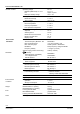
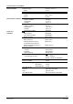
Technical data


14/15
Building Technologies REV200…RF room temperature controller CE1N2214en
HVAC Products 28.08.2008
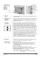
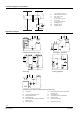
Connection diagram receiver REV-R…
L
Live conductor, AC 230 V
N Neutral conductor, AC 230 V
Lx Live, AC 24...250 V
L1
N.O. contact,
AC 24...250 V / 6 (2.5) A
L2
N.C. contact,
AC 24...250 V / 6 (2.5) A
M1 Circulating pump
N2 Receiver REV-R…
Lx
L1
Y1
M1
N2
Nx
L
N
L2
2255A01
AC 230 V
AC 24...250 V
Lx
Nx
N
L
Y1 Actuating device
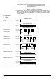
Application examples
T
T
F1
F2
N2
M1
Y2
2255S01
N1
T
F1
F2
N2
M1
Y2
2255S02
T T
T
N1
Instantaneous hot water heater Atmospheric gas burner
N1
Y4
2255S03
Y3
N2
T
N4
T
N3
T
N1
2255S05
E1
N2
Zone valve Cooling equipment
Y1
2252S04
M1
N2
T
N1
Circulating pump with precontrol by manual mixing valve
E1 Cooling unit N3 Room temperature controller (transmitter)
REV200…RF
F1 Thermal reset limit thermostat N4 Receiver REV-R…
F2 Safety limit thermostat Y1 3-port valve with manual adjustment
M1 Circulating pump Y2 Solenoiod valve
N1 Room temperature controller (transmitter)
REV200…RF
Y3 Motorized 3-port valve
N2 Receiver REV-R… Y4 Motorized 2-port valve