
User Manual


8
Siemens
A6V10807602_en
--
_g
Building Technologies 2018-07-17
Product documentation
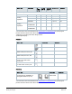
Topic Title Document ID
Mounting and installation Mounting instruction A5W90001424
Installation and operation User guide A6V10877569
Startup wizard Quick guide A5W90001422
CE declaration A5W90002476
Product environmental declaration A5W90003412
Related documents such as environmental declarations, CE declarations, etc., can be
downloaded at: http://siemens.com/bt/download
.
Notes
Security
CAUTION
National safety regulations
Failure to comply with national safety regulations may result in personal injury and property
damage
●
Observe any national provisio
ns and comply with the appropriate safety regulations.
Engineering
See the product documentation for information on engineering, selection and sizing connecting
cables for supply voltage and field devices.
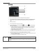
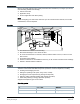
Installation
The mounting plate of the thermostat can be installed on CEE/VDE conduit boxes and on square
boxes 75 x 75 mm. For installation on a rectangular conduit box (e.g. 105 x 72 mm), accessory
ARG100.01 must be ordered, which includes 1 set of white decoration frame and bigger
mounting plate.
WARNING
No internal line protection for supply lines to external consumers
Risk of fire and injury due to short-circuits
● Adapt the line diameters as per local regulations to the rated value of the installed
overcurrent protection device.
● The AC 230 V mains supply line must have an external circuit breaker with a rated current
of no more than 10 A.
● Properly size the cables to the thermostat and for the outputs for AC 230 V mains voltage.
● Use only AC 230 V isolated wired cables, as the conduit box carries AC 230 V mains
voltage.
● Remove wired bridge L - Q11 when loads work with voltages other than AC 230 V.
● Inputs X1-M-X2: Several switches (e.g. window contact) may be connected in parallel.
Consider overall maximum contact sensing current for switch rating.
●
Disconnect from power supply before removing the front of the thermostat.