
User Manual


15
Siemens
A6V10807602_en
--
_g
Building Technologies 2018-07-17
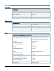
Terminal Use
Q14 Control output; NO contact
Q21 Control input (com)
Q22 Control output; NC contact
Q24 Control output; NO contact
X1, X2, M Multifunctional inputs
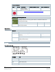
Wiring diagrams
● The thermostat is delivered with one wired bridge ① (L-Q11) for easy installation of
AC 230 V HVAC equipment (example 1).
● When loads use voltages other than AC 230 V, bridge ① must be removed before wiring the
loads to the thermostat (example 2).
● If the load current through Y2 is more than 3 A, bridge between L-Q11 cannot be used.
Adapt parameter “Q22/Q24 electrical load” in “Advanced Settings” / “Optimization”.
● For application with higher currents (Y1 > 3 A or Y2 > 2 A), adapting parameter “Q22/Q24
electrical load” in “Advanced Settings” / “Optimization” accordingly is recommended.
Basic
① AC 230 V
Advanced
Example 1: Loads = AC 230 V
Example 2: Loads Y1, Y2 ≠
AC 230 V
① AC 230 V on Y1, Y2