
User Manual


12
Siemens
A6V10807602_en
--
_g
Building Technologies 2018-07-17
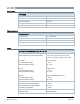
Connections to multifunctional inputs X1 - M - X2
-
Contact sensing
- Parallel connection
- Input function
DC 14…40 V, 8 mA (typ.)
Max. 20 thermostats per switch
Selectable
Outputs
Switching capacity of relay
Voltage Q11, Q12, Q14
Current, min max resistive (inductive)
Potential free, AC 24…230 V
5 mA...5(2) A
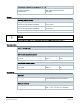
Voltage Q21, Q22, Q24
Current, min max resistive (inductive)
Potential free, AC 24…230 V
5 mA...5(2) A
Note: Connecting different voltages on Q1x and Q2x is allowed (double insulation).
NOTICE
Remove wired bridge L
-
Q11 when loads work with voltages other than AC 230 V.
Operational data
Setpoint setting range
12…35 ℃
Built-in room temperature sensor
Temperature range
0…50 ℃
Accuracy at 25 ℃
±0.5 K
Display resolution
0.5 K
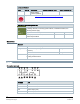
Built-in room humidity sensor
Humidity range
0%...100%
Accuracy at 25 ℃
±5% r.h.
Display resolution
1%
Connections
Interfaces
Micro USB
A service port is limited to firmware upgrades
and onsite diagnosis by professionals.
Wiring connections
Screw terminals Solid wires or prepared stranded wires:
Max. 1 × 0.5... 2.5 mm
2
(14…20 AWG)