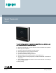
Smart Thermostat RDS110 To control heating applications in apartments, single family homes, dormitories, and other residential as well as commercial spaces.
Room thermostat features ● Direct temperature and operating mode selection ● RoomOptiControl function with Green leaf *) button for energy-optimized operation ● Air quality indication: “Good”, “Okay”, “Poor” ● Temperature setting limitation for use in public spaces ● Screen lock protection against unauthorized access ● Manual switchover between “At home”, “Away” and “OFF” on touch screen ● Room temperature control using the built-in temperature sensor or an optional remote sensor ● Optional temperature aver
● ● ● Monitoring of temperature and humidity Monitoring of indoor air quality: “Good”, “Okay”, “Poor” Secure access and data transmission with the Siemens Cloud Computing Platform Use The RDS110 is designed to control heating applications in apartments, single family homes, dormitories, and other residential as well as commercial spaces.
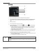
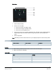
Operation and settings Normal display 1 Tap to display detailed information and additional setting possibilities. 2 Shows if the system is in an energy-optimized mode. If the leaf is red, predefined settings were changed. Tap the red leaf to restore energy-saving mode. The leaf again turns green. 3 Room temperature*) 4 Tap to toggle between “At home” and “Away”. 5 Shows if the thermostat works automatically ( ) or manually ( ).
Idle display 1 Room relative humidity 2 Shows room air quality: ● If the icon is green, air quality is good. ● If the icon is orange, air quality is okay. ● If the icon is red, air quality is poor. 3 Shows if the system is in an energy-optimized mode. If the leaf is red, predefined settings were changed. Tap the red leaf to restore energy-saving mode. The leaf again turns green. 4 Room temperature Note: Depending on how the thermostat is set up, the displayed options in idle mode may differ.
Items Quantity Mounting instructions 1 Activation code sticker 1 Wiring sticker 1 Equipment combinations Remote sensors Type of unit Product no.
Type of unit Product no. LGNi1000 at 0 °C Pt1000 at 0 °C NTC 10k DC 0…10 V Datasheet* at 25 °C Room humidity sensors - Wall-mounted QFA2000 - Wall-mounted including temperature QFA2020 Flush-mounted1) including temperature x 1857 x (r.h.) 1857 QFA2060 x (T+r.h.) 1857 QFA2060D2) x (T+r.h.) 1857 AQR2534ANW x (T) + AQR2540Nx x (r.h.) 1410 AQR2535NNW + AQR2540Nx x (T+r.h.) 1410 x (T) * The documents can be downloaded from http://siemens.
Product documentation Topic Title Document ID Mounting and installation Mounting instruction A5W90001424 Installation and operation User guide A6V10877569 Startup wizard Quick guide A5W90001422 CE declaration A5W90002476 Product environmental declaration A5W90003412 Related documents such as environmental declarations, CE declarations, etc., can be downloaded at: http://siemens.com/bt/download.
Commissioning Refer to the Quick guide and User guide (see Product Documentation) to configure your device. Commissioning includes the following: ● Internet connection ● Application setup ● Account registration and device pairing Note: Before configuring your thermostat, make sure you are connected to the Internet, have a valid email address, and a smartphone. Mounting ● ● ● ● ● ● The devices are suitable for wall mounting. Recommended height: 1.50 m above the floor.
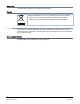
Maintenance The thermostat is designed for maintenance-free operation. Disposal The device is considered an electronic device for disposal in accordance with the European Guidelines and may not be disposed of as domestic garbage. ● Dispose of the device through channels provided for this purpose. ● Comply with all local and currently applicable laws and regulations. Warranty Technical data on specific applications are valid only together with Siemens products listed under "Equipment combinations".
Technical data Power supply Power supply Operating voltage AC 230 V (+10% / -15%) Frequency 48…63 Hz Power consumption Max. 9 VA Standby power consumption (LCD off) 0.6 W Max. external supply line fusing 10 A circuit breaker Radio parameters Radio parameters Frequency band 2.4…2.4835 GHz Maximum radio-frequency power 18 dBm WLAN standard IEEE 802.11b/g/n (HT20) WLAN channel 1~13 Inputs Connections to multifunctional inputs X1 - M - X2 Passive temperature sensors - Cable length max.
Connections to multifunctional inputs X1 - M - X2 - Contact sensing DC 14…40 V, 8 mA (typ.) - Parallel connection Max. 20 thermostats per switch - Input function Selectable Outputs Switching capacity of relay Voltage Q11, Q12, Q14 Current, min max resistive (inductive) Potential free, AC 24…230 V 5 mA...5(2) A Voltage Q21, Q22, Q24 Current, min max resistive (inductive) Potential free, AC 24…230 V 5 mA...5(2) A Note: Connecting different voltages on Q1x and Q2x is allowed (double insulation).
Conformity Ambient conditions and protection classification Safety class as per EN60730 Class II Degree of protection of housing as per EN 60529 IP30 Classification as per EN 60730 Function of automatic control devices Degree of contamination Overvoltage category Type 1 2 III Climatic ambient conditions Storage as per EN 60721-3-1 Class 1K3 Temperature -25...65 °C (-13... 149 °F) Humidity 5...95% Transport (packaged for transport) as per EN 60721-3-2 Class 2K3 Temperature -25...65 °C (-13...
eu.bac certification Type License Application Energy Efficiency Label Control accuracy (K) RDS110 217739 Water heating systems (radiator) AA 0.5 See product list at: http://www.eubaccert.eu/licences-by-criteria.
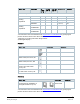
Terminal Use Q14 Control output; NO contact Q21 Control input (com) Q22 Control output; NC contact Q24 Control output; NO contact X1, X2, M Multifunctional inputs Wiring diagrams ● ● ● ● The thermostat is delivered with one wired bridge ① (L-Q11) for easy installation of AC 230 V HVAC equipment (example 1). When loads use voltages other than AC 230 V, bridge ① must be removed before wiring the loads to the thermostat (example 2).
Y1 HVAC equipment B1, B2 External sensors Y2 DHW / Dehumidifier / Humidifier S1, S2 External switches WARNING The total current rating must not exceed 8 A.
Application examples Applications Siemens Building Technologies Gas boiler Electric boiler Radiator with valve Floor heating with valve Radiator with pump Floor heating with pump Electric radiator Electric floor heating Fan with electric heating Key N1 RDS110 B1 Floor temperature sensor Y1 Valve M1 Circulating pump K1 Heat generator (e.g.
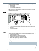
Dimensions RDS110 Front and rear modules Metallic mounting plate ARG100.
Revision history Edition Date Software version Changes Section Pages 5 July 2018 32.2.27 or higher - - - 4 May 2018 32.2.18 or higher ● Added EAC logo Cover page 1 ● Added EAC conformity Technical data 13 ● Updated application names Application examples 3 April 2018 32.2.18 or higher ● Added standby power consumption Technical data figure. 2 January 2018 32.2.18 or higher ● Changed operating modes from Comfort, Pre-comfort and Economy to Comfort, Economy and Unoccupied.
s Issued by Siemens Switzerland Ltd. Building Technologies Division International Headquarters Theilerstrasse 1a CH-6300 Zug Tel. +41 58 724 2424 www.siemens.com/buildingtechnologies 20 Siemens Building Technologies Document ID A6V10807602_en--_g Edition 2018-07-17 © Siemens Switzerland Ltd, 2018 Technical specifications and availability subject to change without notice.