
User Manual


Functions
Additional functions
4
A6V11545892_en--_a 47 | 146
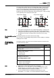
To reduce wear and tear on the HVAC equipment, the minimum output On/Off time
of the Qx relay output can be adjusted (1…20 minutes) via P212 and P213. The
factory setting is 1 minute.
When the operating mode is changed from Comfort to Economy or Protection, the
relay contact remains energized until the end of the minimum on time set via P212.
4.6.4 Monitoring and limitation functions
The floor temperature should be limited for two reasons: Comfort and protection of
the floor.
The floor temperature sensor, connected to multifunctional input X1, X2 or U1,
acquires the floor temperature. If the temperature exceeds the parameterized limit
(P252), the heating valve is fully closed until the floor temperature drops to a level
2 K below the parameterized limit. The factory setting of P252 is 28 ℃.
Input X1, X2 or U1 must be commissioned accordingly (P150, P153, P155 = 11)
and the type of sensor need to be selected (P151, P154, P156 = 2 (NTC 3K) or 3
(LG-Ni1000)).
See Multifunctional input, digital input [➙ 88].
● Living rooms:
Up to 26 °C for long-time presence, up to 28 °C for short-time presence.
● Bathrooms:
Up to 28 °C for long-time presence, up to 30 °C for short-time presence.
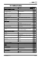
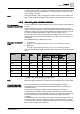
The "Floor temperature limitation" function influences the outputs listed in the table
below:
Application Output
Y1/Y10
Output
Y2/Y20
Output
Y3/Y30
“Floor temp. limit” function has impact on Remark
Heating
(P001 = 0/2/3)
Cooling
P001 = 1/2/3
Heating and
Cooling
(P001 = 4)
2-pipe H/C valve Y1/Y10 N/A
2-pipe with electric
heater
H/C valve Electric
heater
Y2/Y20 Y2/Y20
*)
Only electric
heater
2-pipe with radiator H/C valve Radiator Y2/Y20 Y2/Y20 Only radiator
4-pipe Heating valve Cooling valve Y1/Y10 N/A Y1/Y10
4-pipe with electric
heater
Heating valve Cooling valve Electric
heater
Y3/Y30 N/A Y3/Y30 Only electric
heater
2-pipe/2-stage 1
st
H/C 2
nd
H/C Y1/Y10, Y2/Y20 N/A
*) If P027 = ON, electric heater is in cooling mode.
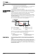
Either floor temperature sensor or external room temperature sensor can be used.
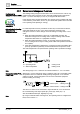
This function increases the comfort in the room by keeping the supply air
temperature of the fan coil unit between the selected minimum and maximum
temperature limits.
If the supply air temperature exceeds a limit, the thermostat reduces the
corresponding valve position until the supply air temperature is back in the limits.
In case the air flow is too low (especially with DC 0...10 V fans), this prevents cold
air from dumping into the room/warm air from bubbling straight up instead of
circulating.
To enable this function, the multifunctional input, to which the supply air sensor is
connected, needs to be set to "Supply air sensor" (for example, P150 = 9). Then
the parameters for the limits are displayed (P063: minimum supply air temperature,
P064: maximum supply air temperature).
Note
Floor temperature
limitation function (P252)
Recommended values for
P252
Note
Supply air temperature
limitation (P063, P064)