
User Manual
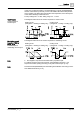
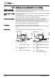
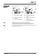
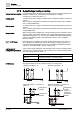
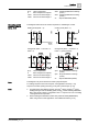

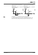

Table Of Contents
- 1 About this document
- 2 Overview
- 3 Notes
- 4 Functions
- 4.1 Temperature control
- 4.2 Operating modes
- 4.3 Room temperature setpoints
- 4.4 Application overview
- 4.5 Power supply selection for RDG200KN
- 4.6 Additional functions
- 4.7 Control sequences
- 4.7.1 Sequence overview (setting via P001)
- 4.7.2 Application mode
- 4.7.3 2-pipe fan coil unit
- 4.7.4 2-pipe fan coil unit with electric heater
- 4.7.5 2-pipe fan coil unit with radiator or floor heating
- 4.7.6 2-pipe/2-stage heating or cooling
- 4.7.7 4-pipe fan coil unit
- 4.7.8 4-pipe fan coil unit with electric heater
- 4.7.9 Chilled/heated ceiling and radiator applications
- 4.7.10 Compressor applications
- 4.7.11 Applications with external AQR sensor or QMX room operator unit
- 4.7.12 Setpoints and sequences
- 4.8 Control outputs
- 4.9 Fan control
- 4.10 Multifunctional input, digital input
- 4.11 Handling system faults
- 4.12 KNX communications
- 4.13 Communication objects (S-Mode)
- 4.14 Communication objects (LTE-Mode)
- 4.15 Control parameters
- 5 Supported KNX tools
- 6 Connection
- 7 Technical data
- 8 Dimensions
- Index /

Functions
Control s
equences
4
A6V11545892_en--_a 67 | 150
Heating mode with manual selection
(P001 = 3) or
for energy saving (P010 = 2 & P014) in
heating sequence
Cooling mode with manual selection
(P001 = 3) or
for energy saving (P010 = 2 & P015) in
cooling sequence
The diagrams only show the PI thermostat’s proportional part.
For setting sequence and control outputs, see Application overview [➙ 37],
Sequence overview (setting via P001) [➙ 56] and Control outputs [➙ 78].
Note