
User Manual
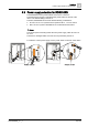


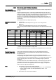
Table Of Contents
- 1 About this document
- 2 Overview
- 3 Notes
- 4 Functions
- 4.1 Temperature control
- 4.2 Operating modes
- 4.3 Room temperature setpoints
- 4.4 Application overview
- 4.5 Power supply selection for RDG200KN
- 4.6 Additional functions
- 4.7 Control sequences
- 4.7.1 Sequence overview (setting via P001)
- 4.7.2 Application mode
- 4.7.3 2-pipe fan coil unit
- 4.7.4 2-pipe fan coil unit with electric heater
- 4.7.5 2-pipe fan coil unit with radiator or floor heating
- 4.7.6 2-pipe/2-stage heating or cooling
- 4.7.7 4-pipe fan coil unit
- 4.7.8 4-pipe fan coil unit with electric heater
- 4.7.9 Chilled/heated ceiling and radiator applications
- 4.7.10 Compressor applications
- 4.7.11 Applications with external AQR sensor or QMX room operator unit
- 4.7.12 Setpoints and sequences
- 4.8 Control outputs
- 4.9 Fan control
- 4.10 Multifunctional input, digital input
- 4.11 Handling system faults
- 4.12 KNX communications
- 4.13 Communication objects (S-Mode)
- 4.14 Communication objects (LTE-Mode)
- 4.15 Control parameters
- 5 Supported KNX tools
- 6 Connection
- 7 Technical data
- 8 Dimensions
- Index /

Functions
Additional functions
4
42 | 150 A6V11545892_en--_a
4.6 Additional functions
Functio
ns (parameters)
Description
RDG260KN
RDG200KN
Sensors and changeover functions
[➙
43
]
●
Heating/cooling changeover via bus (KNX)
Central control of heating / cooling via bus
✓
✓
●
Automatic heating/cooling changeover via
changeover sensor
● Changeover switch (P150, P153, P155)
Thermostat runs sequences depending on the
water temperature
✓
✓
✓
✓
●
Manual heating/cooling changeover
(P001)
Heating / cooling controlled manually by user
(via HMI)
✓
✓
●
External/return air temperature
sensor
(P150, P153, P155)
Temperature measurement using external
sensors
✓
✓
Presence detector
[➙
45
]
●
Standard presence mode (
P1
50
/
P153
/
P155)
Switch operating mode locally or via bus
✓
✓
●
Hotel presence mode (
P150
/
P153
/
P155)
Switch operating mode locally or via bus
✓
✓
Output functions
[➙
46
]
●
Purge function (
P251
)
To ensure correct acquisition of the water
temperature
✓
✓
●
Minimum output On/Off time (
P212
,
P213
)
To protect HVAC equipment, e.g., compressor
and reduce wear and tear
✓
✓
●
Swap outputs f
or 2
-
pipe and 2
-
stage
applications (P254)
To optimize use of heating/cooling energy in
mixed systems
✓
✓
●
Floor heating/cooling (
P350
)
Application without fan control
✓
✓
●
Qx
relay switching function (
P400
,
P401
,
P402)
Control external equipment based on f
unction
state (heating/cooling demand, operating mode,
sequence, humidity, …)
✓
✓
Monitoring and limitation functi
ons
[➙
49
]
●
Flo
or temperature limitation function
(P252)
For user Comfort and floor protection
✓
✓
●
Supply air temperature limitation (
P063
,
P064)
To save energy, by avoiding room air
that is too
hot or cold
✓
✓
●
Flow limitation in heating for PICV (
P256
)
To balance heat
ing and cooling and avoid
hydraulic issues due to different flow rates
✓
✓
●
Dewpoint monitoring
● Fault state “condensation” (P150, P153,
P155 = 4)
To prevent
condensation damage in the building
✓
✓
✓
✓
●
Valve exercising (
P250
)
To prevent valve freezing afte
r extended
inactivity
✓
✓
User operation / Indication
[➙
51
]
●
Button lock (
P028
)
To limit access by unauthorized persons
✓
✓
●
Gre
en leaf (
P110
,
P111
)
Indication on energy efficiency
✓
✓
Humidity
[➙
52
]
●
Humidity control (
P007
,
P450
)
Limit min. and max. humid
ity in the room
✓
✓
Preventive operation
[➙
55
]
●
Avoid cold air in heating mode (
P365
)
To ensure setpoint temperature is reached
during heating
✓
✓
●
Avoid damage from moisture (
P363
,
P364
)
To prevent damages caused by moisture
✓
✓
NFC communication
[➙
55
]
●
N
FC (
P500
)
NFC
communication via Siemens smartphone
application
✓
✓