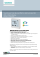
Touch Screen Flush-Mounted PM2.5 & IAQ Controllers With KNX or RS485 Modbus RDF870KN.. and RDF870MB.. PM2.5 control, CO2 control, or both and ventilation applications RDF870KN (KNX) and RDF870MB (Modbus) controllers: ● AC 230 V operating voltage, large, backlit display ● Display and setpoint adjustment for PM2.5 and CO2 control ● Display of room temperature, outside temperature, VOC (volatile organic compound) and r.h.
Use Ventilation control in purifier systems: Typical applications: ● Residential apartments ● Commercial buildings ● Schools/Universities ● Hospitals/Healthcare centers Local and remote configuration via one of the following: ● Local HMI ● DIP switch selection: room controller or room unit RDF870MB only ● Third-party tool Modbus poll/Modbus scan RDF870MB only ● ETS RDF870KN only Functions For room controllers ● Maintain PM2.
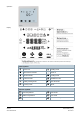
Operation Display Status symbols Screen lock Heating mode Alarm/service reminder Valve on Manual override Cooling mode Protection mode Ventilation mode Auxiliary heating active Auto fan mode Economy mode Timer Selection symbols Room temperature VOC mode Outdoor temperature CO2 mode PM2.
Operational icons Increment, decrement or selection Selection, change or move to previous or next items Display values, relative humidity or parameter values, etc. Secondary display, parameters, password / filter hours Setpoint mode Fan mode or fan speed mode Operating mode More functions or info Type summary Product no. Stock no.
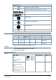
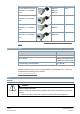
Type of units Product number Data sheet*) Duct air quality sensor CO2/ QPM1100, N1962 temperature / rel. humidity / QPM2100, VOC QPM2102 Duct air quality sensor CO2/ QPM2102D N1962 Duct air quality sensor CO2/ QPM2160, N1962 temperature / rel. humidity / QPM2180 temperature / rel. humidity / VOC VOC Duct air quality sensor CO2/ QPM2160D, temperature / rel. humidity / QPM2162D N1962 VOC *) All documents can be downloaded from https://www.downloads.siemens.com/downloadcenter.
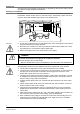
Engineering See the product documentation for information on engineering, selection and sizing connecting cables for supply voltage and field devices. Mounting and installation Mount the room controller on a conduit box. Do not mount on a wall in niches or between bookshelves, behind curtains, above or near heat sources, wind outlets or inlets, and do not expose to direct solar radiation. Mount about 1.5 m above the floor.
● ● ● Isolate the cables of Modbus communication input A+, B- and REF for 230 V. (Only for RDF870MB) No cables are provided with a metal shield. Disconnect from supply before opening the cover. Commissioning After powering up, all LCD segments light up for about three seconds before the room controller enter its normal states. Address and application can be downloaded via ETS by pressing and holding for more than five seconds to enter programming mode.
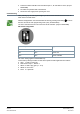
Software version (RDF870KN) Two different software versions of RDF870KN are available: ● RDF870KN with software version (U101): Related ETS5 file (RDF870KN_v1d0_ETS5.knxprod) ● RDF870KN with software version (U103): Related ETS5 file (RDF870KN_v1d1_ETS5.knxprod) The software version can be checked as follows: ● The software version relates to production date (DDMMYYYY) on the individual package label or printed on the rear of the product. E.g.
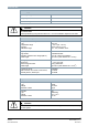
Technical data Power supply Operating voltage AC 230 V Frequency 50/60 Hz. Power consumption Max. 7.0 VA / 2.5 W CAUTION On internal fuse. External preliminary line protection with max. C 10 A circuit breaker required in all cases. Multifunctional input X1-M/X2-M Temperature sensor input: Type Temperature range Accuracy Calibration range NTC 10k 0…50 °C (32…122 °F) ±0.5 K at 25 °C (77 °F) -5 K…5 K, resolution 0.
KNX interface KNX type Bus current KNX TP1-64, galvanic isolation. 5 mA Modbus interface Modbus type Transmit mode Connection Baud rate Modbus address Cable length Identity Transmission format (start bit – data – parity – stop) RS485 RTU Support up to 32 9600, 19200 (default), 38400 1-247, 1 (default) Max.1200 meters Slave 0 = 1-8-E-1 (default) / 1 = 1-8-O-1 / 2 = 1-8N-1 / 3 = 1-8-N-2 Wiring connections Diameter Wire 1.
Standards, directives and approvals RCM conformity A5W90010386 (RDF870KN) *) A5W90010387 (RDF870MB) *) REACH Regulation (EC) No 1907/2006 Registration, Evaluation, Authorisation and Restriction of Chemicals (REACH) RoHS Directive 2011/65/EU restriction of the use of certain harzardous substances in electronic equipment Environmental compatibility The product environmental declaration (A6V11625786 *) contains data on environmentally compatible product design and assessments (RoHS compliance, materials
Diagrams Connection terminals RDF870KN RDF870MB X1 Multifunction input 1 M Input reference ground for X1, X2 and Y50 X2 Multifunction input 2 Y50 DC 0…10 V output CE+, CE- KNX bus + and - terminals REF Modbus reference ground A+, B- Modbus + and - terminals L, N AC 230 V operating voltage Q1 Output, fan speed 1, AC 230 V Q2 Output, fan speed 2, AC 230 V Q3 Output, fan speed 3, AC 230 V Q4 Output, fan speed 4, AC 230 V 12 Siemens Smart Infrastructure A6V11439454_en--_d 2021-03-31
Connection diagrams RDF870KN Single fan 3-speed fan 4-speed fan ECM fan RDF870MB (room controller) Single fan 3-speed fan 4-speed fan ECM fan 13 Siemens Smart Infrastructure A6V11439454_en--_d 2021-03-31
RDF870MB (room unit) L, N AC 230 V operating voltage X1, X2 Multifunctional inputs 1 & 2 (sensor, alarm, etc.) M Input reference ground for X1, X2 and Y50 CE+, CE- KNX bus + and - terminals Q1, Q2, Q3, Q4 Four speeds fan output (relay output) Y50 DC 0…10 V output REF Modbus reference ground A+, B- Modbus + and - terminals M1 1-speed, 3-speed or 4-speed fan, DC 0...
Application examples CO2 application (single duct single fan) Single duct single fan fresh air unit or purifier with built-in PM2.5 filter Basic parameter settings: APP = 3, DISP (CO 2 = 1), SEN1 =4, FAN =1-/3-/4-speed on/off fan or ECM fan RDF870… unit can be set up as a CO2 controller with an external CO 2 sensor connected to X1 to control the fan for a fresh air unit (i.e. single duct single fan fresh air unit with/without PM2.5 built-in filter).
PM2.5 application (single duct single fan) Single duct single fan purifier with built-in PM2.5 filter Basic parameter settings: APP = 1, DISP (PM2.5 = 1), SEN1 =3, FAN =1-/3-/4-speed on/off fan or ECM fan RDF870... unit can be set up as a PM2.5 controller with an external PM2.5 sensor connected to X1 to control the fan for a PM2.5 purifier unit (i.e. single duct single fan purifier with PM2.5 built-in filter). The purifier is not connected to external but installed on the ceiling.
CO2 application (dual duct parallel connected fan) Dual duct parallel connected fan fresh air unit or purifier with built-in PM2.5 filter Basic parameter settings: APP = 3, DISP (CO 2 = 1), SEN1 =4, FAN =1-/3-/4-speed on/off fan or ECM fan RDF870… unit can be set up as a CO2 controller with an external CO 2 sensor connected to X1 to control the fan operation of a fresh air unit (i.e. dual duct parallel connected fan fresh air unit with/without PM2.5 built-in filter).
PM2.5 & CO2 room unit application (dual duct independent fan control together with a master controller) Dual duct independent fan fresh air unit or purifier with built-in PM2.5 filter via by-pass damper Basic parameter settings: APP = 2, DISP (PM2.5 = 1, CO 2 = 1), SEN1 = 3, SEN2 = 4, FAN1 & FAN2 =1-/3-speed on/off fan RDF870... unit can be set up as a controller combining PM2.5 and CO2 control with an external PM2.
Parameters Parameter mode user access 2. Enter first password via or 1. Touch & hold icon > 5 s PAS: Password 3. Enter second password via Factory: 00 00 or 4. After 6 seconds Note: Press the Setting icon to exit or re-enter the password if not correct P: Successful login F: Failed login 5. Edit parameters Value of current selected parameter Decrement or Previous available value Previous parameter Increment or Next available value current selected Parameter Next parameter 6.
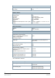
Engineering parameters Item Description Range Factory settings MODA Modbus address setting 1…247 1 MODB Modbus baud rate setting 1: 9600 bps 2: 19200 bps 3: 38400 bps 2: 19200 bps MODF Modbus data frame format 0: 1/8/E/1 1: 1/8/O/1 2: 1/8/N/1 3: 1/8/N/2 0: 1/8/E/1 APP Application selection 1: PM2.5 control only 2: PM2.5 + CO2 control 3: CO2 control only 4: Ventilation 1: PM2.
Item Description TEMH Temperature sensor high range Max. of low range…100 50 TEML Temperature sensor low range -50…Min. of high range 0 SPMH PM2.5 setpoint high range Max. of low range…500 100 SPML PM2.5 setpoint low range 0…Min. of high range 12 SPCH CO2 setpoint high range Max. of low range…2000 1500 SPCL CO2 setpoint low range 0…Min.
Firmware setpoint settings Item Description Range Factory settings TCSP Filter time setting 0…9999 8760 PM2.5 SP PM2.5 setpoint SPML…SPMH 60 CO2 SP CO2 setpoint SPCL…SPCH 1000 T SP Temperature setpoint T SP L…T SP H 24 T SP H Temperature setpoint range high Max. of low range…200 (°C) 50 T SP L Temperature setpoint range low -50…Min. of high range (°C) 5 VOC SP VOC setpoint %: 0…100 mg/m3: 0…5 0.
Expert mode parameters Item Description Range Factory settings PMP PM2.5 control factor Xp 0…1000 50 PMI PM2.5 control factor Tn 0…120 min 45 min CO2P CO2 control factor Xp 0…2000 100 CO2I CO2 control factor Tn 0…120 min 45 min PMDB PM2.
KNX S-Mode communication objects (RDF870KN) Overview Object no. and name RDF870… Object no. and name 8 Room operating mode: State 9 Room operating mode: State Comfort 10 Room operating mode: State Eco 11 Room operating mode: State Protection 4 Room operating mode user: Preselection 5 Room operating mode user: Preselection Comfort 6 Room operating mode user: Preselection Eco 7 Room operating mode user: Preselection Protection 16 PM2.5 setpoint user 17 CO2 setpoint user 18 PM2.
Description of communication objects Object no. Object name Function Type/length Flags 1 Alarm information 219.001 6 Byte CT Fault information Common alarm output. If an alarm occurs, the alarm number is transmitted. 2 Fault state Faulty/normal 1.005 1 bit CT 1.003 1 bit CWU Common alarm output. If an alarm occurs, the alarm flag is set. 3 Enable alarm info Enable/disable A supervisor alarm system can disable the broadcasting of alarms by the devices.
Object no. Object name Function Type/length Flags Note: Outside temperature value is decided by the priority order if all value types exist. (X1/X2 > Remote) 15 Remote: Outdoor temperature Temperature value 9.001 2 Bytes CWU AQ Setpoint value 9.030 2 Bytes CWTU 9.008 2 Bytes CWTU AQ Setpoint value 9.030 2 Bytes CRT AQ Setpoint value 9.008 2 Bytes CRT Temperature value 9.001 2 Bytes CRT Remote outside temperature sensor value 16 PM2.5 setpoint user One AQ setpoint value from a HMI.
Object no. Object name Function Type/length Flags 5.004 2 Bytes CRT AQ value 9.030 2 Bytes CWU CO2 value 9.008 2 Bytes CWU AQ value 9.030 2 Bytes CWU AQ value 5.004 2 Bytes CWU 0…100% 5.001 8 bit CWU Indicate the value of the room VOC value Note: Room VOC value, priority order is X1/X2 > Remote 27 Room VOC[%] Room AQ value Indicate the value of the room VOC value Note: Room VOC value, priority order is X1/X2 > Remote 28 Remote: PM2.5 Remote PM2.
Modbus communication objects (RDF870MB) Description of communication objects Default Value Data Value Range RW 0x03 0x06 1 1 1…247 2 Modbus baudrate 40002 1 RW 0x03 0x06 1 2 1: 9600bps 2: 19200bps 3: 38400bps 3 Modbus format 40003 1 RW 0x03 0x06 1 0 0: 1/8/E/1 1: 1/8/O/1 2: 1/8/N/1 3: 1/8/N/2 4 Application 40004 1 RW 0x03 0x06 1 1 1: PM2.5 control only 2: PM2.
1 0 0: (no function) 1: Temperature (AI) (NTC 10k) 2: Temperature (AI) (0…10 V) 3: PM2.
Default Value Data Value Range RW 0x03 0x06 1 60 0…100 36 CO2 ECO setpoint 40036 1 RW 0x03 0x06 1 1000 500…1500 37 Reserved 3 40037 1 RW 0x03 0x06 1 0 0…ffff 38 Buzzer 40038 1 RW 0x03 0x06 1 1 0: Disable 1: Enable 39 Temperature unit 40039 1 RW 0x03 0x06 1 0 0: °C (degrees Celsius) 1: °F (degrees Fahrenheit) 40 7) Keylock 40040 1 RW 0x03 0x06 1 0 0: Unlock 1: Locked 2: Setpoint only 3: Operating mode only 4: Setpoint and fan speed only 41 Operation mode
Default Value Data Value Range RW 0x03 0x06 2 60 SPML…SPMH 60 CO2 setpoint 40102 1 RW 0x03 0x06 2 1000 SPCL…SPCH 61 Local DO1 40103 1 RW 0x03 0x06 2 0 0: Off: 1: On 62 Local DO2 40104 1 RW 0x03 0x06 2 0 0: Off: 1: On 63 Local DO3 40105 1 RW 0x03 0x06 2 0 0: Off: 1: On 64 Local DO4 40106 1 RW 0x03 0x06 2 0 0: Off: 1: On 65 Room temperature source 40107 1 RW 0x03 0x06 2 1 0: Built in temperature; 1: Remote 66 Current working mode 40108 1 RW 0x0
Data Value Range Default Value Special process Multi Register Group Identification Write Function code 0x03--Read Single Holding Register 0x04--Read RO Register 0x06--Write Single Holding Register Read only (RO) or Read/Write (RW) Object length (bytes) Object Register Address (Decimal) Object no.
Data Value Range Default Value Special process Multi Register Group Identification Write Function code 0x03--Read Single Holding Register 0x04--Read RO Register 0x06--Write Single Holding Register Read only (RO) or Read/Write (RW) Object length (bytes) Object Register Address (Decimal) Object no. Read Bit3: AL2; Bit4: Clean filter; Bit5: Built-in sensor error; Bit6: EEPROM error; Bit7: X1/X2 error 99 PM2.
Data Value Range Default Value Special process Multi Register Group Identification Write Function code 0x03--Read Single Holding Register 0x04--Read RO Register 0x06--Write Single Holding Register Read only (RO) or Read/Write (RW) Object length (bytes) Object Register Address (Decimal) Object no.
Dimensions (mm) 35 Siemens Smart Infrastructure A6V11439454_en--_d 2021-03-31
Issued by Siemens Switzerland Ltd Smart Infrastructure Global Headquarters Theilerstrasse 1a CH-6300 Zug +41 58 724 2424 www.siemens.com/buildingtechnologies Document ID A6V11439454_en--_d Edition 2021-03-31 © Siemens Switzerland Ltd, 2019 Technical specifications and availability subject to change without notice.