
User Manual

83 / 92
Siemens………………..RDF301, RDF301.50..., RDF600KN, RDF600KN/VB, RDF600KN/S Basic Documentation CE1P3171en
Smart Infrastructure 2020-02-21
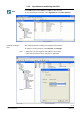
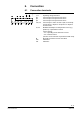
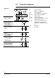
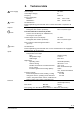
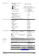
ACS provides standard plant diagrams for RDF KNX thermostats, which depend
on the configuration as follows:
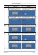
· Plant type
Application
Configuration
Application
Configuration
2-pipe 2-pipe fan coil unit
– Control sequence: No impact (P01 = any)
– Fan operation: Not disabled (P52 <> 0)
Radiator*
– Control sequence: Heating only (P01 = 0)
– Fan operation: Disabled (P52 = 0)
Chilled / heated ceiling*
– Control sequence: Changeover (P01 = 2,3)
– Fan operation: Disabled (P52 = 0)
Chilled ceiling*
– Control sequence: Cooling only (P01 = 1)
– Fan operation: Disabled (P52 = 0)
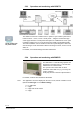
2-pipe and
electric
heater
2-pipe fan coil unit with electric heater
– Control sequence: No impact (P01 = any)
– Fan operation: Not disabled (P52 <> 0)
Single stage with electric heater
– Control sequence: No impact (P01 =any)
– Fan operation: Disabled (P52 = 0)
4-pipe 4-pipe fan coil unit
– Control sequence: Not auto c/o (P01 <> 3)
– Fan operation: Not disabled (P52 <> 0)
Chilled ceiling with radiator*
– Control sequence: No impact (P01 =any)
– Fan operation: Disabled (P52 = 0)
Fan coil unit main / secondary
– Control sequence: Auto c/o (P01 = 3)
– Fan operation: Not disabled (P52 <> 0)
Main / secondary
– Control sequence: Auto c/o (P01 = 3)
– Fan operation: Disabled (P52 = 0)
* Not applicable for RDF301 and RDF301.50.