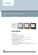
Heating or Cooling only Room Thermostat RDD510 For heating or cooling only units A6V11881086_en--_b 2020-05-20 ● LCD backlit display ● Keylock function ● Display either room temperature or setpoint ● Comfort and Protection(Off) operating modes ● Timer with delay Off function: preset or user selection from 1 to 23 hours ● Minimum and maximum setpoint limitation ● Return to previous operating mode or Protection(Off) upon power down ● Internal sensor calibration ● Adjustable commissioning a
Use To control the room temperature in individual rooms using: ● Heating or cooling only equipment (RDD510) The thermostats control: ● One on/off valve actuator Functions ● ● ● ● ● ● ● ● ● Maintenance of room temperature via built-in temperature sensor Control sequence Heating or Cooling only selection (P01) Operating mode selection via button Display either room temperature value or setpoint value (P06) Internal sensor calibration (P05) Minimum and maximum setpoint limitation (P09&P10) Full or partial key
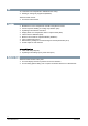
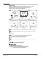
Operating and setting elements 1. Keylock activated 6. Operating mode selection: On, Off, timer with delay Off 2. Timer with delay Off mode 7. 3 key buttons to adjust setpoints and operating modes while 2 non-functional key buttons are required for parameter mode and other access 3. Cooling mode selected 8. Temperature setpoint adjustment 4. Valve output energized 9. Temperature value 5. Heating mode selected 10.
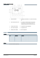
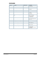
Equipment combinations Type of units Product number Data Sheet Electromotoric ON/OFF valve and actuator (only available in AP, UAE, SA and IN) MVI.../MXI... A6V11251892 Electromotoric ON/OFF actuator SFA21... N4863 Thermal actuator (for radiator valve) STA23... N4884 STA73... N4884 Thermal actuator AC 230 V (for small valves 2.5 mm) , NC STP23... N4884 Thermal actuator AC 24 V STP73... N4884 Zone valve actuators (only available in AP, UAE, SA and IN) SUA... N4832 Damper actuator GDB.
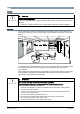
Notes Security CAUTION National safety regulations Failure to comply with national safety regulations may result in personal injury and property damage ● Observe any national provisions and comply with the appropriate safety regulations. Mounting Do not wall-mount in niches or bookshelves, behind curtains, above or near heat sources, wind outlets or inlets, and do not expose to direct solar radiation. Mount about 1.5 m above the floor.
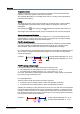
Commissioning After powering up, the thermostat resets and all LCD segments light up for about 3 seconds. Afterwards, the room temperature is displayed (factory setting) and the unit is ready for commissioning by qualified HVAC staff. The thermostat’s control parameters can be adjusted to ensure optimum performance of the entire system (see “Parameter settings”). Surge protection at power-up When the thermostats are powered up, LCD display and key buttons work normally except all valve outputs, e.g.
2. The control output was energized for more than the “Minimum output on time”; (factory setting 1 minute) Note: ● Control output Y12 delivers a control command which is inverted to the control command at output Y14 that can be used for normally open valves. ● Valve output can respond immediately and does not consider minimum On/Off time if users manually adjust the setpoint via local HMI. Error handling Temperature out of range Factory setting of the heating/cooling setpoint in Protection mode is Off, i.e.
Control parameters Parameter settings To optimize control performance, use the local HMI to adjust a number of control parameters. All control parameter settings are retained after power down. Proceed as follows to change the control parameters: Press and hold down the + and - buttons simultaneously for more than 3 seconds. Release the buttons, and within 2 seconds, press and hold down the + button for 3 seconds. P01 is displayed. Press < or > to access the desired parameter and press the √ button.
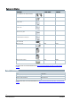
Control parameters Parameter Description Factory setting Setting range P01 Control sequence RDD510 = 0 0:= Heating only 1:= Cooling only P05 Sensor calibration 0K -5…+5 K P06 Standard temperature display 0 0:= Room temperature 1:= Setpoint P09 Minimum setpoint in Comfort mode 5℃ 5…40 ℃ P10 Maximum setpoint in Comfort mode 35 ℃ 5…40 ℃ P14 Keylock function 0 0:= No lock 1:= Full lock 2:= Partial lock P27 Operating mode settings upon power down 0 0:= Return to previous operating
Operation Temperature control The thermostat acquires the room temperature via its built-in sensor and maintains the setpoint by delivering 2-position valve control commands. The switching differential is 1 K in heating mode and 1 K in cooling mode (adjustable via parameters P30 and P31). Display The display shows the current room temperature or the setpoint of the current operating mode (adjustable via parameter P06). Factory setting is to display the current room temperature.
Keylock Keylock can be activated or deactivated via parameter P14 when the thermostat is in Comfort and Protection mode. Either full lock (P14=1) or partial lock (P14=2) can be selected. All buttons are disabled if full lock is set. On partial lock, only setpoints can be adjusted. Operating modes The following operating modes are available: Comfort mode In Comfort mode, the thermostat maintains the setpoint, which can be adjusted via the + and - buttons.
Warranty Technical data on specific applications are valid only together with Siemens products listed under "Equipment combinations". Siemens rejects any and all warranties in the event that third-party products are used.
Technical data Power supply Operating voltage AC 230 V (+10%, -15%) Frequency 50/60 Hz Power consumption Max. 12 VA Internal fuse (replaceable) Fuse type SLOW-BLOW Size dia. 5.2x20 mm Voltage rating 250 V Current rating 6.3 A Outputs Valve output (RDD510) Y12 (N.C.)/Y14 (N.O.) AC 230 V Rating 5 mA…4(2) A Operational data Switching differential - Heating mode 0.5...6 K (factory setting: 1 K) - Cooling mode 0.5...
All documentations can be downloaded from https://www.downloads.siemens.com/download-center/. *) General Connection terminals Solid wires or prepared stranded wires: 1x0.4-1.
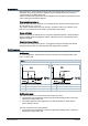
Connection diagrams RDD510 Example 1: with SUA21/3 Siemens Smart Infrastructure N1 RDD510 L, N AC 230 V power supply, mains and neutral V1 On/Off valve V2 On/Off valve: Siemens SUA21/3 V3 ON/Off valve: third party 3-wire valve Y12 SPDT relay output, normally closed Y14 SPDT relay output, normally open T 6.3 A Internal fuse (6.
Application examples Heating ● ● ● Floor heating Radiators Wall-hung boilers Room thermostat controls the valve of the floor heating or radiator application Room thermostat directly controls a gas-fired wall-hung boiler Cooling Room thermostat directly controls cooling equipment N1 16 Siemens Smart Infrastructure Room thermostat Y1 2-port valve E1 Cooling equipment A6V11881086_en--_b 2020-05-20
Dimensions Dimensions in mm View A View B Above are the dimensions for the thermostat and its mounting plate.
Issued by Siemens Switzerland Ltd Smart Infrastructure Global Headquarters Theilerstrasse 1a CH-6300 Zug Tel. +41 58 724 2424 www.siemens.com/buildingtechnologies 18 Siemens Smart Infrastructure Document ID A6V11881086_en--_b Edition 2020-05-20 © Siemens Switzerland Ltd, 2020 Technical specifications and availability subject to change without notice.