Datasheet Smart Thermostat Receiver RCR114.1 Smart Thermostat Receiver works with RDS110.R. ● ● Mains-powered receiver AC 230 V Configurable as a relay or wireless repeater via DIP switch – Configurable as a relay to control heating equipment – Configurable as a wireless repeater to extend Thread® network coverage ● A6V11562464_en--_b 2021-07-16 Communication with RDS110.
Use The RCR114.1 works as a router-eligible end device (REED) in the network created by RDS110.R. It can function as a relay or wireless repeater. If working as a relay, it can control the following heating equipment: ● Gas boiler ● Radiator with pump ● Electric floor heating ● Fan with electric heating ● Floor heating with valve ● Floor heating with pump ● Electric radiator ● Electric boiler ● Generic heating device If working as a wireless repeater, it acts as a bridge to connect RDS110.R and RCR114.
Wireless repeater If an RCR114.1 (working as a relay box) or SSA911.01TH is installed too far away from the RDS110.R, another RCR114.1 (working as a wireless repeater) should be added in between to extend the network coverage. See Mounting [▶ 5] for details. NOTE: 1. DIP Switch 2 is reserved for internal use only. 2. One RDS110.R can pair up with at most 3 repeaters and 6 relays to extend the network coverage. 3. The RCR114.1 powers up automatically after it is connected to the mains voltage.
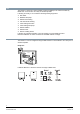
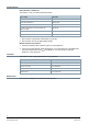
1 LED for indication of operating status 2 Button for user operation Type summary Type Stock number Description RCR114.1 S55772-T104 Smart Thermostat Receiver Ordering When ordering, indicate product number, stock number and description. Equipment combinations Room thermostats Product number Stock number Description RDS110.R S55772-T103 Smart Thermostat Wireless Product number Stock number Description SSA911.01TH S55181-A101 Smart Valve Actuator Wireless actuator NOTE: The RDS110.
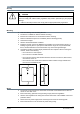
Notes Security CAUTION National safety regulations Failure to comply with national safety regulations may result in personal injury and property damage. ● Observe national provisions and comply with the appropriate safety regulations. Mounting ● ● ● ● ● ● ● ● Note the following when mounting the unit: The device is suitable for wall and surface mounting. Enclose the conductors in a conduit when surface mounting. Reserve sufficient free space for ventilation (see the following picture).
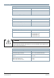
Commissioning LED indication on RCR114.1 The RCR114.1 has one LED to indicate its status. Device status LED status Idle Solid yellow Connecting to RDS110.R Flashing green Successful connection Solid green Thread® network works, but communication with RDS110.R failed1) Flashing red Thread® network failure2) Solid red Factory reset Alternating red and green 1. Reconnection is performed automatically or manually. 2. Reconnection can only be performed manually. Manual network reconnection 1.
Disposal The device is considered an electronic device for disposal in accordance with the European Guidelines and may not be disposed of as domestic garbage. ● Dispose of the device through channels provided for this purpose. ● Comply with all local and currently applicable laws and regulations. Warranty Technical data on specific applications are valid only together with Siemens products listed under "Equipment combinations".
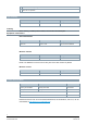
Technical data Power supply Operating voltage AC 230 V (+10/-15%) Frequency 48…63 Hz Power consumption 5 VA Maximum external supply line fusing 10 A circuit breaker Radio parameters Frequency band 2.4…2.4835 GHz Maximum radio-frequency power 15 dBm Media Access Control and Physical Layer 802.15.
Electrical connections Connection terminals Screw terminals For solid wires 2 x 1.5 mm2 For stranded wires 1 x 2.5 mm2 (Min. 0.
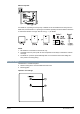
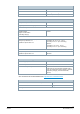
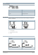
Diagrams Connection terminals Terminal Designation L, N Power supply, AC 230 V Q11, Q21 Control input (com) Q12, Q22 Control output, NC contact Q14, Q24 Control output, NO contact Wiring diagrams Example 1 illustrates a convenient wiring method (AC 230 V with bridge). If the load is not AC 230 V, see example 2.
Applications Floor heating with pump Electric radiator Electric floor heating Fan with electric heating Domestic hot water boiler N1 RDS110.R N2 RCR114.
Y2 Domestic hot water boiler Y3 Valve M1 Circulating pump Dimensions 12 Siemens Smart Infrastructure A6V11562464_en--_b 2021-07-16
Issued by Siemens Switzerland Ltd Smart Infrastructure Global Headquarters Theilerstrasse 1a CH-6300 Zug +41 58 724 2424 www.siemens.com/buildingtechnologies Document ID A6V11562464_en--_b Edition 2021-07-16 © Siemens Switzerland Ltd, 2021 Technical specifications and availability subject to change without notice.