QSA2700D / QSA2700 / AQS2700 Fine dust room sensor Basic Documentation A6V11160936_en--_c 2019-04-10 Smart Infrastructure
Table of Contents 1 1.1 1.2 1.3 About this document ............................................................................. 5 Revision history ...........................................................................................5 Reference documents..................................................................................5 Before you start ...........................................................................................5 2 2.1 2.2 2.3 2.4 2.5 Product overview ...............
A6V11160936_en--_c 6 6.1 6.2 6.3 6.4 Maintenance ...................................................................................... 33 Replacing AQS2700 ..................................................................................33 Proximity sensor (QSA2700D) ...................................................................34 Troubleshooting .........................................................................................35 Disposal .....................................................
About this document Revision history 1 1 About this document 1.1 Revision history Edition Date Changes Section c 2019-03 Add information about “Modify Modbus ● settings” ● Normal display overview Modbus register ● Push button configuration ● Change display value ● Change theme ● Analog output range selection ● Modbus configuration ● Modify Modbus settings b 2018-01 Frequency Technical data a 2017-12 First version. All 1.2 Reference documents Ref.
1 About this document Before you start WARNING This is the symbol for hazard. It warns you of Risks of injury. Comply with all measures designated by this symbol to prevent injury or death. NOTICE This symbol identifies an important notice that you should be aware of when you are using the product. Document use/ request to the reader 6 | 40 Before using products from Siemens Switzerland Ltd.
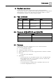
Product overview 2 Type summary 2 Product overview The fine dust room sensor is designed to measure and transmit indoor concentrations of PM2.5 and PM10. This wall-mounted product has variants with or without displays and can connect directly to Siemens BT controllers as well as many third party controllers via voltage output or Modbus. 2.1 Type summary Type Order number Description Display QSA2700 S55720-S457 Room sensor for detection of PM2.
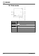
2 Product overview Device overview 2.
Product overview Normal display overview of QSA2700D 2 2.5 Normal display overview of QSA2700D PM2.5 in μg/m3 PM2.5 & PM10 in μg/m3 PM2.5 & PM10 in μg/m3 + 24 hours trend PM2.5 & PM10 in μg/m3 and particles/m3 1 PM2.5 value in μg/m3 2 The current Air Quality Index category 3 PM2.
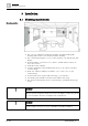
3 Installation Mounting requirements 3 Installation 3.1 Mounting requirements Mounting position ● ● ● ● ● ● ● ● ● The sensor is suitable for conduit box mounting, dry wall mounting (with mounting hole for wires concealed) and surface mounting. The recommended height is 1.2-1.5 m above the floor, especially for type with display. Do not mount the sensor in recesses, shelves, behind curtains or doors, or above heat sources. Avoid direct solar radiation.
Installation Wiring 3 Mounting dimensions ● ● ● Mounting tools Wire specification Wire stripper Screw driver Pencil, level & drill (for dry wall mounting and surface mounting only) Wires for Specifications Power supply 0.4 to 1.5 mm2 Analog output 0.4 to 1.5 mm2 Modbus output Twisted pair 0.4 to 1.5 mm2 Length <600m 3.2 Wiring G, G0: Operating voltage AC 24 V (SELV) / DC 13.5…35 V U1: Signal output DC 0...10 V for PM2.5 with selected range in μg/m3 U2: Signal output DC 0...
3 Installation Installation 3.3 Installation 1. Separate the housing from the mounting plate using a screw driver. 2. Screw and fix the mounting plate on a conduit box (Conduit box mounting), or on a wall (Dry wall mounting if there is a mounting hole and the wires are concealed in the hole; Surface mounting if there is no mounting hole).
Installation 3 Installation 3. Connect and screw wires correctly to the terminal. For surface mounting, you must break out the wiring hole at the top or bottom first. 4. Attach the housing to the mounting plate at the top and then snap on the housing at the bottom.
4 Configurations Modbus configuration parameters 4 Configurations 4.1 Modbus configuration parameters The sensor is a Modbus (RS485) slave device, configurable via a Modbus master. Configurable Name Range / Enumeration Default Address 1...
Configurations 4 Modbus registers (Software version 1.3.13) Holding Register (16-bit) No. Name Description Default R/W 764 Modbus address 1…247 1 R/W 765 Baud rate 1= 9600bps; 2 R/W 0 R/W 0 R/W 2 = 19200bps; 3 = 38400bps; 4 = 57600bps 766 Transmission format (start bit – data bits – parity – stop bit) 0 = 1-8-E-1; 1 = 1-8-O-1; 2 = 1-8-N-1; 3 = 1-8-N-2 768 Bus configuration command 0 = Ready; 1 = Load; 2 = Discard Remarks: ● The register number is counted from 1.
4 Configurations Modbus registers (Software version 1.3.13) Holding Register (16-bit) No. Name Description Default R/W 206 Number of particles PM1.0…PM2.5 In pcs for particle size between 1.0…2.5 micron R 207 Number of particles PM2.5…PM5.0 In pcs for particle size between 2.5…5.
Configurations Modbus registers (Software version 1.3.13) 4 Remarks: ● The register number is counted from 1. ● The precondition for valid displays of temperature (register 217) and r.h. (register 218) is as below: – Register 221 is enabled. – Display value “PM2.5 & PM10 in μg/m3” is selected as display format. – Register values are transmitted from the master. ● In the case of a multiple writing command from the master with invalid values, the sensor rejects the command with an error notice.
4 Configurations Push button configuration (QSA2700) 4.4 Push button configuration (QSA2700) 4.4.1 On-event addressing (ClimatixTM controllers configuration) On-event addressing is a rapid configuration approach working together with Siemens ClimatixTM controllers. The sensor is wired and connected to the Climatix TM controller via Modbus.
Configurations 4 LED colors and patterns (QSA2700) 4.4.2 Reset Modbus parameter Reset Modbus settings or cancel resetting Press the LED Action More details 1…5 s Constant red Press and hold the button 5…10 s LED off Press and hold the button 10…13 s Flash yellow Reset Modbus setting to factory default if releasing the button 1) button for Release the button while the LED still flashes yellow. LED keeps flashing yellow for 3 s. then turns red for 1 s. The reset is completed.
4 Configurations Initial setup (QSA2700D) Step Description 1 Power on the device: Page 1 is displayed. Picture Then in page 1: 1. Short press to select the language. 2. Long press (>2 s) to save the selection and then enter next page ( page 2). Page 1 2 From page 1, long press (>2 s) to enter page 2. Then in page 2: 1. Short press to select among the different 2. Long press (>2 s) to save the selection and then enter next page ( page 3). classes.
Configurations Change settings 4 4.7 Change settings The following device settings can be changed: ● Language ● Air Quality Index class ● Display format ● Theme In the following change setting steps: ● short press means short press the push button ● long press (>2 s) means long press the push button (2…10 s) 4.7.1 Change language (QSA2700D) Step 1 Description Picture From page 4, short press to enter page 5. Then in page 5: ● Short press to enter next page (page 6).
4 Configurations Change settings 4.7.2 Change Air Quality Index class (QSA2700D) Step 1 Description Picture From page 5: short press to enter page 6. Then in page 6: ● Short press to enter next page (page 7). ● Long press (>2 s) to enter page 6-1. Page 6 2 In page 6-1: 1. Short press to select an Air Quality Index 2. Long press (>2 s) to save the selection and back to page 6. class.
Configurations Change settings 4 4.7.3 Change display format (QSA2700D) Step 1 Description Picture From page 6: short press to enter page 7. Then in page 7: ● Short press to enter next page (page 8). ● Long press (>2 s) to enter page 7-1. Page 7 2 In page 7-1: 1. Short press to select a display value format. 2. Long press (>2 s) to save the selection and back to page 7. Page 7-1 3 From page 7, short press to enter page 8.
4 Configurations Change settings Step Description Picture Page 10 Page 11 Page 12 24 | 40 A6V11160936_en--_c
Configurations Analog output range selection (QSA2700D) 4 4.7.4 Change theme (QSA2700D) Step 1 Description Picture From page 7, short press to enter page 8. Then in page 8: ● Short press to enter next page (selected normal display, e.g. page 3). ● Long press (>2 s) to enter page 8-1. Page 8 2 In page 8-1: 1. Short press to select a theme color. 2. Long press (>2 s) to save the selection and back to page 8. Page 8-1 4.
4 Configurations Modbus configuration (QSA2700D) Step 1 Description Picture From selected normal display e.g. page 3, long press (>2 s) to enter page 13. Page 3 2 From page 13, short press to enter page 14. For Modbus configuration, refer to Modbus configuration (QSA2700D) [➙ 26]. Page 13 3 In page 14: ● Short press to enter next page (page 3). ● Long press (>2 s) to enter page 14-1. Page 14 4 In page 14-1: 1. Short press to select a range. 2.
Configurations Modbus configuration (QSA2700D) Step 1 Description 4 Picture From selected normal display e.g. page 3, long press (>2 s) to enter page 13. Page 3 2 In page 13: ● Short press to enter next page (page 14). ● Long press (>2 s) to enter page 15. Page 13 3 In page 15, short press to select desired operation: 1. “Modify Modbus settings”: local manual configuration 2. “Configure via Climatix”: plug&play with Climatix 3. “Reset Modbus settings”: reset to factory default 4.
4 Configurations Modbus configuration (QSA2700D) Step Description 3.3 When “Reset Modbus Settings” is selected, long press (>10 s) to activate the function. Picture Page 15-2 4.9.1 Modify Modbus settings (QSA2700D) Step 1 Description Picture From page 15, long press (>2 s) to enter page 16 Page 15 2 In page 16: ● Short press to enter next page (page 17). ● Long press (>2 s) to enter page 16-1. Page 16 3 In page 16-1: 1. Short press to select baudrate. 2.
Configurations Modbus configuration (QSA2700D) Step Description 4 From page 16, short press to enter page 17. 4 Picture Then in page 17: ● Short press to enter next page (page 18). ● Long press (>2 s) to enter page 17-1. Page 17 5 In page 17-1: 1. Short press to select transmission format. 2. Long press (>2 s) to save the selection and back to page 17. Page 17-1 6 From page 17, short press to enter page 18. Then in page 18: ● Short press to enter next page (page 18-2).
4 Configurations Modbus configuration (QSA2700D) Step Description 6.1 In page 18-1, ● Short press to change the values for first ● Long press (>2 s) to save the change and back to page 18. Picture digital. Tip: Only 0, 1, and 2 are available for first digital. Page 18-1 6.2 From page 18, short press to enter page 18-2. Then in page 18-2: ● Short press to enter next page (page 18-3). ● Long press (>2 s) to modify the values for second digitals same as step 6.1. Page 18-2 6.
Technical data Power supply 5 5 Technical data 5.1 Power supply Operating voltage AC 24 V ±20% / DC 13.5…35 V Frequency 50/60 Hz @ AC 24 V Power consumption 4 VA 5.2 Functional data for PM2.5 Measuring range (selectable) ● 0…500 μg/m3 ● 0…300 μg/m3 ● 0…100 μg/m3 ● 0…50 μg/m3 Unit to unit variability Max of ±15 μg/m3 and ±15% of reading @ 25 °C and 50% r.h. Analog output signal, (terminal U1) DC 0...10 V, linear, corresponding to selected measuring range 5.
5 Technical data Operation conditions 5.6 Operation conditions Temperature 0…50 °C Humidity 5...95% r.h. (no condensation) 5.7 Storage and transportation conditions Temperature -20…70 °C Humidity 0…95% r. h. (no condensation) 5.8 Standards Electromagnetic compatibility CE standard EN 60730-1 Immunity EN 61 000-6-2 Emissions EN 61 000-6-3 EU conformity declaration A6V11277342 *) *) The document can be downloaded at http://siemens.com/bt/download. 5.
Maintenance Replacing AQS2700 6 6 Maintenance 6.1 Replacing AQS2700 Replace the sensor module due to: ● Reaching its end of lifetime: as indicated via LED or LCD, and output signal. Refer to Troubleshooting [➙ 35] for the indication. ● The measurement is not as accurate as specified. The sensor still works but is indicated via LED or LCD. Refer to Troubleshooting [➙ 35] for the indication. Sensor module accuracy is influenced by ambient environment.
6 Maintenance Proximity sensor (QSA2700D) NOTICE Turn off the device before replacing the sensor module. If not possible, insert a new sensor module 10 s after the old one is removed. 6.2 Proximity sensor (QSA2700D) QSA2700D includes a built-in proximity sensor and enters into energy efficient mode if no obstacle is detected in front of the sensor (approximately 1 m) over the past few minutes.
Maintenance Troubleshooting 6 6.3 Troubleshooting Error QSA2700D QSA2700D Description 0-10 V output Replace sensor module when: Present 0 V (2 Value of register s) and 10 V (2 209 changes s) one by one in from 0 to 1 turn 1. it is broken; 2. it reaches its lifetime. Modbus Check for: 1. 2. QSA2700D Present 0 V (5 Value of register the communication s) and 10 V(5 s) 209 changes one by one in from 0 to 2 error between sensor module and turn product MCU; missing sensor module.
7 Air Quality Index classes 7 Air Quality Index classes The Siemens fine dust sensor QSA2700D displays: ● The PM2.5 reading in μg/m3 ● The AQI (Air Quality Index) The AQI is a number used by government agencies to communicate to the public how polluted the air currently is or a forecast of air quality. The AQI category (good, moderate, unhealthy, etc.) is based on the AQI (see Table 1) and is represented by a range of colors (green = good, orange = poor, etc.).
Standard compliance 8 8 Standard compliance 1. The product complies with CE standard (EN 61000-6-2, EN 61000-6-3, EN 60730-1). 2. The product complies with the RoHS and RoHS CN standard.
9 Appendices Cyber security disclaimer 9 Appendices 9.1 Cyber security disclaimer Siemens provides a portfolio of products, solutions, systems and services that includes security functions that support the secure operation of plants, systems, machines and networks. In the field of Building Technologies, this includes building automation and control, fire safety, security management as well as physical security systems.
Appendices Cyber security disclaimer A6V11160936_en--_c 9 39 | 40
Issued by Siemens Switzerland Ltd Smart Infrastructure Global Headquarters Theilerstrasse 1a CH-6300 Zug +41 58 724 2424 www.siemens.com/buildingtechnologies A6V11160936_en--_c © Siemens Switzerland Ltd, 2017 Technical specifications and availability subject to change without notice.