
User Manual

CM1N5483E / 10.1998 Siemens Building Technologies
4/8 Landis & Staefa Division
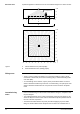
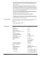
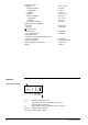
Spatial arrangement of detection zones for an installation height of 3 m above the floor.
- 5
- 4
- 3
- 2
- 1
0
1
2
3
4
5 m
- 5 - 4 - 3 - 2 - 1 0 1 2 3 4 5 m
- 5 - 4 - 3 - 2 - 1 0 1 2 3 4 5 m
A
B
5483Z02
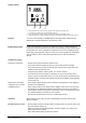
3 m
2
1
0
30˚ (diagonal 23˚)
A Normal detection zone (seated people)
B Extended detection zone (walking people)
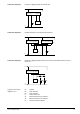
• The detector locations specified in the planning documentation must not be changed.
• There is a choice of fitting the detector on a recessed conduit box (using a single
conduit box of 58 mm dia.) and surface mounting (using a standard mounting frame
of 50 mm depth).
• To avoid damage to the detector, only the power part should be fitted. The actual
detector should be installed only at the time of commissioning. The optical part of the
detector should be handled with care. No pressure must be exerted on the plastic
insert!
•
Prior to commissioning, it must be made certain that the wiring is in compliance with
the plant diagram.
• The required brightness for the control of the lighting system and the switch on and
switch off delays for HVAC control must be set with the respective potentiometers at
the rear of the unit as specified.
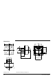
• The detector should be fitted to the power part without applying any force! When
fitting, bar, terminal block and the inscription can be used as an orientation aid. To
Detection zones
Legend
Fitting notes
Commissioning
notes