
User Manual


Siemens Building Technologies CM1N5482E / 10.1998
Landis & Staefa Division 5/8
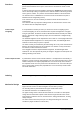
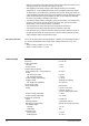
Spatial arrangement of detection zones.
55˚
48˚
39˚
29˚
22˚
16˚
9,5˚ 3,5˚
5482Z03
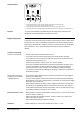
• The detector locations specified in the planning documentation must not be changed.
• There is a choice of fitting the detector on a recessed conduit box (using a single
conduit box of 58 mm dia.) and surface mounting (using a standard mounting frame
of 50 mm depth).
• To avoid damage to the detector, only the power part should be fitted. The actual
detector should be installed only at the time of commissioning. The optical part of the
detector should be handled with care. No pressure must be exerted on the plastic
insert!
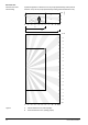
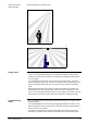
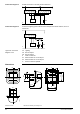
• When fitting the QPA82.1 to the ceiling of corridors exceeding 1.5 m in width, the
asymmetric pattern of the detection zone must be taken into consideration. In that
case, it is recommended to install the detector off the middle of the corridor. The front
of the detector must face the closest wall (refer to illustration «Ceiling mounting»).
•
Prior to commissioning, it must be made certain that the wiring is in compliance with
the plant diagram.
• The required brightness for the control of the lighting system and the switch on and
switch off delays for HVAC control must be set with the respective potentiometers at
the rear of the unit as specified.
• The detector should be fitted to the power part without applying any force! When
inserting, the inscription can be used as an orientation aid. To avoid damage when
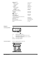
Detection zone with
ceiling mounting
Fitting notes
Commissioning
notes