
Installation Instructions

Document No. 129-435
Installation Instructions
February 18, 2016
Information in this publication is based on current specifications. The company reserves the right to make changes in specifications and
models as design improvements are introduced. Product or company names mentioned herein may be the trademarks of their respective
owners. © 2016 Siemens Industry, Inc.
Siemens Industry, Inc.
Building Technologies Division
1000 Deerfield Parkway
Buffalo Grove, IL 60089
USA
+ 1 847-215-1000
Your feedback is important to us. If you have
comments about this document, please send them to
SBT_technical.editor.us.sbt@siemens.com
Document No. 129-435
Printed in the USA
Page 4 of 4
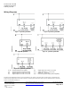
Wiring Diagrams
Figure 7. QPA2080, QPA2080D. Figure 8. QPA2060, QPA2060D.
Figure 9. QPA2000. Figure 10. QPA2062, QPA2062D.
Figure 11. QPA2002, QPA2002D.
G, G0 System potential 24 Vac (SELV) U3 Signal output 0 to 10 Vdc or 0 to 5 Vdc
G0 System neutral and measuring neutral R..(*) Signal output with R...= 0 to 10 Vdc;
U1 Signal output 0 to 10 Vdc or 0 to 5 Vdc without R... = 0 to 5 Vdc
U2 Signal output 0 to 10 Vdc or 0 to 5 Vdc B, M Passive temperature output (interchangeable)