
Installation Instructions

Document No. 129-435
Installation Instructions
February 18, 2016
Page 2 of 4 Siemens Industry, Inc.
Installation, Continued
· Away from drafts caused by doors, windows,
outside walls, air registers, pipes, return air
plenums, and so on.
· Away from heat sources, such as strong lights,
fireplaces, direct sunlight, and so on.
· On an inside wall (preferably), about 5 feet
(1.5 m) above the finished floor.
NOTES: Local codes (such as the Americans
with Disabilities Act) may require a
specific mounting height.
The end of the conduit at the sensor
must be sealed to prevent
inaccurate measurements due to
drafts through the conduit.
Drywall Mounting (No Rough-in), Typical
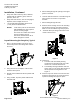
1. Place a small screwdriver into the top of the
sensor and press in the locking tab to remove
the cover.
Figure 1.
2. Using the base as a template, mark the hole
locations with a pencil.
3. Drill two 1/4-inch diameter holes for plastic wall
anchors.
4. Using a mallet, tap in the plastic wall anchors
flush with wall.
Figure 2.
5. Pull the wiring through the opening in the upper
portion of the base.
6. Level the base and fasten it to the wall using two
wood screws. The sensor is not position
sensitive.
7. Pull the wiring through the base.
8. Position sensor housing over the two mounting
lugs located at the top of the base and press
down on cover until bottom lugs snap in place.
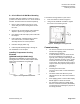
9. Terminate wires per wiring instructions on the
inside of sensor cover.
Figure 3.
10. Check that:
a. The wires from the humidity sensing
membrane are separated from each other
and are not in contact with the PCA.
b. The humidity sensing membrane has "free
space" and is not in contact with the PCA or
the temperature sensing element. See
Figure 3.
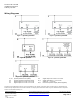
11. Insert the top of the sensor cover into the slots
located on the bottom of the sensor and press
up until the locking tab snaps into place.
Figure 4.
The installation is now complete.