
Data Sheet for Product


Technical Instructions QPA20xx Series Indoor Air Quality Room Sensors
Document Number CE1N1961
July 26, 2019
Page 4 Siemens Industry, Inc.
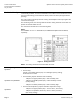
Mechanical Design
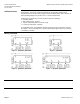
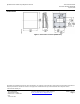
These are wall-mounted units, and they are designed for use with most types of
commercially available, recessed conduit boxes. The cables can be introduced from the
rear (concealed wiring) or from below or above (surface-run wires) through knockout
openings.
The units consist of two major sections: Casing and baseplate. Both snap together but
can be detached again.
The measuring circuit, the sensing elements and the setting elements are located on a
printed circuit board inside the unit.
The connection terminals are on the mounting base.
NOTE:
For installation on a 2” × 4” electrical box, an ARG70 base plate must be ordered,
separately.
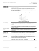
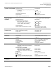
Figure 3. Setting Elements.
NOTE: The setting elements are located inside the cover.
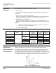
Measuring Range
QPA2000
Meaning of the different jumper positions:
• For CO
2
only:
Jumper in the middle position (R2) = 0 to 2000 ppm (factory setting).
R1 and R3 are not used.
QPA2002 and QPA2002D
• For CO
2
/VOC, jumpers determine VOC sensitivity:
− Jumper in the upper position (R1) = VOC sensitivity "low".
− Jumper in the middle position (R2) = VOC sensitivity "normal"
(factory setting).
− Jumper in the lower position (R3) = VOC sensitivity "high".
QPA206xx
• For CO
2
and temperature, jumpers determine temperature range:
− Jumper in the upper position (R1) = -31°F to 95°F (−35 to 35°C).
− Jumper in the positions (R2 or R3) = 32°F to 122°F (0 to 50°C)
(R2, factory setting).