
Basic Documentation
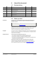
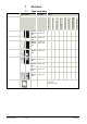
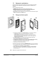
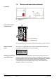
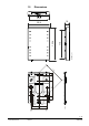
Table Of Contents
- Wall-mounted sensors and room operator units for KNX/ETS and KNX/ACS
- Contents
- 0 About this document
- 1 Devices
- 2 Safety and EMC optimization
- 3 Mounting and electrical installation
- 4 Functionality / Use
- 5 ETS engineering
- 5.1 Engineering
- 5.2 Commissioning
- 5.3 Communication objects
- 5.4 Room operator unit visualization and operation
- 5.5 ETS parameter description
- 5.5.1 Room temperature sensor
- 5.5.2 Room temperature control
- 5.5.3 Room relative humidity sensor
- 5.5.4 Room relative humidity control
- 5.5.5 Room air quality sensor
- 5.5.6 Room air quality control
- 5.5.7 Device display parameters
- 5.5.8 HVAC operation and display
- 5.5.9 Operation and display: Relative humidity visualization
- 5.5.10 Display on QMX3.P70 Air quality indication LED
- 5.5.11 Operation and display: air quality
- 5.5.12 Operation of light, shading and scenes
- 5.6 Examples for the operation of touch keys and display elements
- 6 ACS engineering

8 / 46
Siemens Wall-mounted sensors and room operator units for KNX/ETS and KNX/ACS CM2N1602en_07
Smart Infrastructure Devices 2020-06-20
1.4 Service and connection elements
R1 QMX3... Room operator unit
N1 Controller, actor
Twisted pair
Service LED (red)
Programming pin
The service element functions are described Commissioning, sections 5.2 and 6.2.
The devices are supplied with peel-off adhesive address labels containing the
unique KNX ID as alphanumeric and barcode display.
The address label can be peeled off the device during mounting and stuck to a
floor plan or similar. The floor plan thus contains the assignment of KNX IDs and
physical installation location. This greatly simplifies the following steps. In addition,
the procedure serves as the basis for the recommended engineering and
commissioning process. If the adhesive labels are lost, all information is still
available in printed form on the housing.
Connection
Service LED (red) and
programming pin
Adhesive address
labels
Simplifyin
g engineering
and commissioning