
Basic Documentation
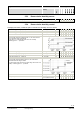
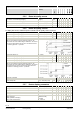
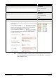
Table Of Contents
- Wall-mounted sensors and room operator units for KNX/ETS and KNX/ACS
- Contents
- 0 About this document
- 1 Devices
- 2 Safety and EMC optimization
- 3 Mounting and electrical installation
- 4 Functionality / Use
- 5 ETS engineering
- 5.1 Engineering
- 5.2 Commissioning
- 5.3 Communication objects
- 5.4 Room operator unit visualization and operation
- 5.5 ETS parameter description
- 5.5.1 Room temperature sensor
- 5.5.2 Room temperature control
- 5.5.3 Room relative humidity sensor
- 5.5.4 Room relative humidity control
- 5.5.5 Room air quality sensor
- 5.5.6 Room air quality control
- 5.5.7 Device display parameters
- 5.5.8 HVAC operation and display
- 5.5.9 Operation and display: Relative humidity visualization
- 5.5.10 Display on QMX3.P70 Air quality indication LED
- 5.5.11 Operation and display: air quality
- 5.5.12 Operation of light, shading and scenes
- 5.6 Examples for the operation of touch keys and display elements
- 6 ACS engineering

44 / 46
Siemens Wall-mounted sensors and room operator units for KNX/ETS and KNX/ACS CM2N1602en_07
Smart Infrastructure ACS engineering 2020-06-20
6 ACS engineering
6.1 Engineering
Tool ACS790 is used for engineering with devices from the Synco 700 range. This
tool is documented in Service- and Operating software ACS790 [5].
For ACS790, version 8.23 or higher must be installed.
During room operator unit mounting, the address labels can be peeled off the
devices and stuck to a floor plan or similar to show the KNX IDs and the physical
location in one place.
After mounting/installation, the devices are detected after updating the ACS790
device list. The devices can be easily identified in the device list based on the
collected KNX IDs, and the physical addresses can be assigned as planned. As a
result, commissioning requires only very little effort.
6.2 Commissioning
Depending on the environment, both type and number of adjustable parameters
will vary. Prior to commissioning, all devices must be mounted as per the mounting
instructions [2] and connected to bus cabling. If available, pushbuttons and
external temperature sensors must also be connected to the device. Bus cabling
must be tested.
Pushbutton actuation Meaning
Short (< 0.5 s) Switch over to programming mode or acknowledge display of a
connection test.
No functions are executed when the programming button is
pressed longer (> 0.5 s to 2 s).
Long (> 20 s) Reset to factory settings.
LED indication Meaning
Orange Feedback on special mode.
Red Device is in programming mode.
All other indication types are irrelevant for KNX LTE-Mode.
Room sensor QMX3, KNX LTE–Mode controllers, and operator units are
connected to power. Update first the ACS790 device list, then open.
à Variant 1 (recommended)
1. Select a room operator unit from the device list via the KNX ID
(KNX-IDs must be collected during mounting).
2. Double-click this line to open the "Address assignment" dialog.
or
ACS
790 version
Recommendation:
Keep the adhesive
address labels
Commissioning
prerequisites
Pu
shbutt
ons
LED status indication
Commissioning with
ACS