
Basic Documentation
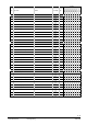
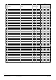
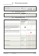
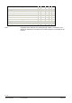
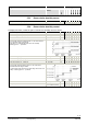
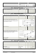
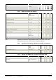
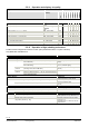
Table Of Contents
- Wall-mounted sensors and room operator units for KNX/ETS and KNX/ACS
- Contents
- 0 About this document
- 1 Devices
- 2 Safety and EMC optimization
- 3 Mounting and electrical installation
- 4 Functionality / Use
- 5 ETS engineering
- 5.1 Engineering
- 5.2 Commissioning
- 5.3 Communication objects
- 5.4 Room operator unit visualization and operation
- 5.5 ETS parameter description
- 5.5.1 Room temperature sensor
- 5.5.2 Room temperature control
- 5.5.3 Room relative humidity sensor
- 5.5.4 Room relative humidity control
- 5.5.5 Room air quality sensor
- 5.5.6 Room air quality control
- 5.5.7 Device display parameters
- 5.5.8 HVAC operation and display
- 5.5.9 Operation and display: Relative humidity visualization
- 5.5.10 Display on QMX3.P70 Air quality indication LED
- 5.5.11 Operation and display: air quality
- 5.5.12 Operation of light, shading and scenes
- 5.6 Examples for the operation of touch keys and display elements
- 6 ACS engineering

38 / 46
Siemens Wall-mounted sensors and room operator units for KNX/ETS and KNX/ACS CM2N1602en_07
Smart Infrastructure ETS engineering 2020-06-20
Designation Values Type
Visible parameter name in ETS Range
(Default)
Unit
QMX3.P30
QMX
3.P40
QMX3.P7
0
QMX3.P34
QMX3.P
44
QMX3.P74
QMX3.P37
QMX3.P02
5.5.5 Room air quality sensor
CO
2
concentr.: Send following change by
5;10;20…500;750;1000
(10ppm)
ppm X X
CO
2
concentr.: Sensor correction (ppm) -500…+500 (0 ppm) ppm X X
CO
2
concentr.: Send cyclically after 1;2;3…30;45;60 (15 min) min X X
CO
2
concentr.: Altitude above sea level (m) 0…5000 (0 m) min. X X
5.5.6 Room air quality control
To display this section, enable the option “Activate room air quality control” in Device
Default switching point stage 1 (ppm) 400…2000 (800) ppm X X X X X X X X
Default switching point stage 2 (ppm) 400…2000 (1000) ppm X X X X X X X X
Default switching point stage 3 (ppm) 400…2000 (1500) ppm X X X X X X X X
Hysteresis 50…500 (100) ppm X X X X X X X X
If the CO
2
concentration exceeds a switching point CO
2
, the
control value CO
2
for the related stage is switched on. The control
value CO
2
is again switched off, if the CO
2
concentration returns
to < switching point CO
2
– hysteresis.
Control value stage 0 (%) 0…100 (0) % X X X X X X X X
Control value stage 1 (%) (>stage 0) 0…100 (35) % X X X X X X X X
Control value stage 2 (%) (>stage 1) 0…100 (70) % X X X X X X X X
Control value stage 3 (%) (>stage 2) 0…100 (100) % X X X X X X X X
If the CO
2
concentration exceeds a switching point CO
2
, the
control value CO
2
for the related stage is switched on. The control
value issues again the value of the next lower stage when CO
2
concentration < switching point CO
2
– hysteresis.
Stage when overridden 0;1;2;3 (3) X X X X X X X X
Send cyclically after
Do not send cyclically
1;2;3...30;45;60 (15 min)
min. X X X X X X X X
5.5.7 Device display parameters
Backlight Level 0; 10;…100 (60%) % X X X X
Backlight idle time 3…20 (15 s) s X X X X
Active unit set °C; °F (°C) X X X X
Active audio feedback (buttons) yes; no (yes) X X X X
LED Brightness 0…100 (100) % X X
Display: Idle page
(HVAC operation and display)
Temperature
Relative humidity
Air quality
X X X X
Time to return to idle page (s) 3…120 (15 s) s X X X X