
Basic Documentation
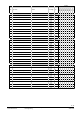
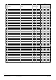
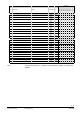
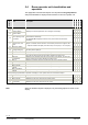
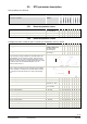
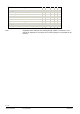
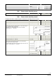
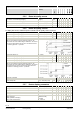
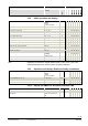
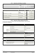
Table Of Contents
- Wall-mounted sensors and room operator units for KNX/ETS and KNX/ACS
- Contents
- 0 About this document
- 1 Devices
- 2 Safety and EMC optimization
- 3 Mounting and electrical installation
- 4 Functionality / Use
- 5 ETS engineering
- 5.1 Engineering
- 5.2 Commissioning
- 5.3 Communication objects
- 5.4 Room operator unit visualization and operation
- 5.5 ETS parameter description
- 5.5.1 Room temperature sensor
- 5.5.2 Room temperature control
- 5.5.3 Room relative humidity sensor
- 5.5.4 Room relative humidity control
- 5.5.5 Room air quality sensor
- 5.5.6 Room air quality control
- 5.5.7 Device display parameters
- 5.5.8 HVAC operation and display
- 5.5.9 Operation and display: Relative humidity visualization
- 5.5.10 Display on QMX3.P70 Air quality indication LED
- 5.5.11 Operation and display: air quality
- 5.5.12 Operation of light, shading and scenes
- 5.6 Examples for the operation of touch keys and display elements
- 6 ACS engineering

35 / 46
Siemens Wall-mounted sensors and room operator units for KNX/ETS and KNX/ACS CM2N1602en_07
Smart Infrastructure ETS engineering 2020-06-20
5.5 ETS parameter description
Factory settings are in brackets
Designation Values Type
Communication objects available in ETS
when function is enabled
Range
(Default)
Unit
QMX3.P30
QMX
3.P40
QMX3.P7
0
QMX3.P34
QMX3.P
44
QMX3.P74
QMX3.P37
QMX3.P02
5.5.1 Room temperature sensor
Room temperature: Sensor correction –5…+5 °C
in 0.1 steps (0 °C)
K X X X X X X X X
Room temperature: Send following change by 0.1…2.5 °C (0.1 °C) K X X X X X X X X
Room temperature: Send cyclically after 1…60 (2 min) min X X X X X X X X
5.5.2 Room temperature control
To display this section, enable the option “Activate room temperature control” in Device
Activate room temperature control yes; no X X X X X X X X
Heating type* Radiator heating slow
(Radiator heating fast)
Floor heating slow
Floor heating fast
X X X X X X X X
Cooling type (Chilled ceiling)
Floor cooling
X X X X X X X X
Parameters heating / cooling type allow for adapting the controller to
the type of heating / cooling. In addition, the controller features two
control algorithms: one for continuous mode (0..100%) and one for
PWM mode (On/Off). The mode is selected via parameter "Control
value type". The control value type is identical for all operating modes.
In continuous mode, the associated PWM output is "On" at
continuous control value ≠ 0.
In PWM mode, cycle time and pulse width are adapted to the type of
heating / cooling, the setpoint, and the measured room temperature.
The min. cycle time is 12 minutes, the min. pulse width is 4 minutes.
The continuous control value issues 0% or 100% in this operating
mode.
Default heating setpoint 5…40 (21.0) °C X X X X X X X X
Default cooling setpoint 5…40 (24.0) °C X X X X X X X X
Control value type (PWM)
Continuous 0…100%
X X X X X X X X
Send cyclically after Do not send cyclically
1;2;3...30;45;60
min X X X X X X X X
Protection heating setpoint 5…40 (12.0) °C X X X X X X X X
Economy heating setpoint 5…40 (15.0) °C X X X X X X X X
Precomfort heating setpoint 5…40 (19.0) °C X X X X X X X X
Comfort heating setpoint 5…40 (21.0) °C X X X X X X X X
Comfort cooling setpoint 5…40 (24.0) °C X X X X X X X X
Precomfort cooling setpoint 5…40 (28.0) °C X X X X X X X X
Economy cooling setpoint 5…40 (35.0) °C X X X X X X X X
Protection cooling setpoint 5…40 (40.0) °C X X X X X X X X
Comfort extension time 5…120 (30) min X X X X X X X X
Number of window status inputs 0…4 X X X X X X X X