
Basic Documentation
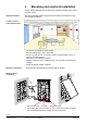
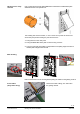
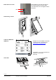
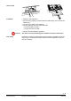
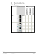
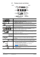
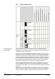
Table Of Contents
- Wall-mounted sensors and room operator units for KNX/ETS and KNX/ACS
- Contents
- 0 About this document
- 1 Devices
- 2 Safety and EMC optimization
- 3 Mounting and electrical installation
- 4 Functionality / Use
- 5 ETS engineering
- 5.1 Engineering
- 5.2 Commissioning
- 5.3 Communication objects
- 5.4 Room operator unit visualization and operation
- 5.5 ETS parameter description
- 5.5.1 Room temperature sensor
- 5.5.2 Room temperature control
- 5.5.3 Room relative humidity sensor
- 5.5.4 Room relative humidity control
- 5.5.5 Room air quality sensor
- 5.5.6 Room air quality control
- 5.5.7 Device display parameters
- 5.5.8 HVAC operation and display
- 5.5.9 Operation and display: Relative humidity visualization
- 5.5.10 Display on QMX3.P70 Air quality indication LED
- 5.5.11 Operation and display: air quality
- 5.5.12 Operation of light, shading and scenes
- 5.6 Examples for the operation of touch keys and display elements
- 6 ACS engineering

18 / 46
Siemens Wall-mounted sensors and room operator units for KNX/ETS and KNX/ACS CM2N1602en_07
Smart Infrastructure Functionality / Use 2020-06-20
4.3 Display elements and buttons
Button Button
1
2
3
4
5
6
7
8
· An arrow indicates that an element can be operated
· Temperature display in °C or °F / humidity in % r.H. /
air quality in text, symbol, or ppm of CO
2
· Toggling (key 1) between indoor and outdoor measurement
(temperature, humidity, CO2)
· Indication that a window is open (connected window switch is active)
· Display of the plant state (Heating or Cooling / inactive)
Note: No manual switchover!
· Display of the relative or absolute setpoint for temperature (Comfort)
Setpoints for room humidity and room CO
2
concentration.
· Adjusting the setpoint using keys 2 and 6
· Display of the present fan speed (when automatic)
· Adjusting the fan speed using key 3 (or keys 3 and 7 if operation of room
operating mode is disabled)
· Display of the room operating mode (when automatic)
· Adjusting the room operating mode using key 7
· Navigation: toggle the display / setpoint setting between temperature /
humidity / CO
2
, using key 4. The black bar points to the displayed
information.
· Operation of the occupancy state (presence switch, Comfort extension)
· Activate the Comfort extension using key 8 (only available if enabled)
· Engineering functions (press keys 1 and 8 simultaneously during 5 s)
– Programming mode (key 2), same function as programming pin
(service pin) on the back of the device
– Connection test (Key 3) (not supported by ETS and ACS)
– Reset device to factory settings (key 4)
NOTICE
T
his operation is irreversible!
· Indicates that the room operator unit is locked by the system.
– Operation is disabled
– The display in line 1 shows the temperature from bus
A
B