
Basic Documentation
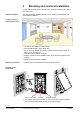
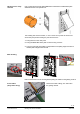
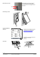
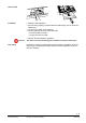
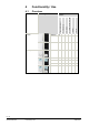
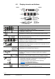
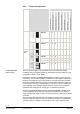
Table Of Contents
- Wall-mounted sensors and room operator units for KNX/ETS and KNX/ACS
- Contents
- 0 About this document
- 1 Devices
- 2 Safety and EMC optimization
- 3 Mounting and electrical installation
- 4 Functionality / Use
- 5 ETS engineering
- 5.1 Engineering
- 5.2 Commissioning
- 5.3 Communication objects
- 5.4 Room operator unit visualization and operation
- 5.5 ETS parameter description
- 5.5.1 Room temperature sensor
- 5.5.2 Room temperature control
- 5.5.3 Room relative humidity sensor
- 5.5.4 Room relative humidity control
- 5.5.5 Room air quality sensor
- 5.5.6 Room air quality control
- 5.5.7 Device display parameters
- 5.5.8 HVAC operation and display
- 5.5.9 Operation and display: Relative humidity visualization
- 5.5.10 Display on QMX3.P70 Air quality indication LED
- 5.5.11 Operation and display: air quality
- 5.5.12 Operation of light, shading and scenes
- 5.6 Examples for the operation of touch keys and display elements
- 6 ACS engineering

15 / 46
Siemens Wall-mounted sensors and room operator units for KNX/ETS and KNX/ACS CM2N1602en_07
Smart Infrastructure Mounting and electrical installation 2020-06-20
· Follow the KNX regulations
· For KNX wiring (topology, allowed cables and cable length), see the document
KNX bus [6].
· Use the correct cables for the KNX bus
· Do not interchange the wires of the KNX cable.
– The red terminal is for KNX +
– The gray terminal is for KNX –
· Observe all local installation regulations.
The devices are not protected against accidental connection to AC 230 V.
Information in topology and addressing in KNX networks is available in document
KNX bus [6]. The following information requires electrical installation as per the
KNX-TP1 standard.
Remo
ve label
Installation
Caution!
Bus cabling
1
602J110
1
6
0
2
Z
1
0
7