
User Manual
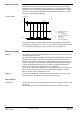
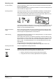
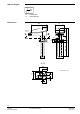

Table Of Contents

2/6
Siemens Duct Hygrostats QFM81… CM1N1514E
Smart Infrastructure 2020-12-21
The hygrostat acquires the relative humidity of the air with its humidity sensor, which is a
stabilized plastic texture strip. The strip actuates a microswitch with a fixed switching
differential X
d
and a potential-free contact output (S.P.D.T.), depending on the relative
humidity of the air. If the actual humidity deviates from the adjusted setpoint, the hygro-
stat switches the associated humidification or dehumidification equipment on or off as
shown in the following function diagram.
r.h. Relative humidity in %
S1 Microswitch
1-2 Humidification
1-3 Dehumidification
w Setpoint
x Actual value
X
d
Switching differential
If the relative humidity exceeds the adjusted setpoint, the potential-free contact of the
microswitch will change over from 1-2 to 1-3. If the relative humidity falls by the amount
of the fixed switching differential X
d
, the contact will return to the position 1-2.
The hygrostat consists of base with immersion sensor stem and cover. The cover is se-
cured to the base with a screw.
The stem accommodates the temperature-compensated humidity sensing element (sta-
bilized plastic texture strip). The strip is mechanically linked to the microswitch via a
transfer lever. Transfer lever, microswitch, setpoint setting element and connection ter-
minals for connecting the humidification or dehumidification equipment are mounted on
a printed circuit board inside the base. The connection terminals are protected by a
hinged cover to avoid direct access when the cover is removed.
The cover has a hole for the setpoint knob. The hygrostat is designed for mounting in air
ducts, but can also be mounted on a wall. For both mounting methods, a mounting
flange is required, which is supplied with the unit.
Same design as the QFM81.2, but with an additional transparent cover on the hole for
the setpoint knob, cable gland Pg 11, and seal under the unit cover.
On both units, the setpoint is adjusted with the setpoint knob. The setting scale is on the
unit cover.
With the QFM81.21, the setpoint can be adjusted only when the cover is removed.
Mode of operation
Function diagram
X
d
t
t
1
3
2
w
x
S1
r. h. [%]
1514D01E
Mechanical design
QFM81.2
QFM81.21
Setting elements
Setpoint knob