
Data Sheet for Product

Technical Instructions QBM81-… Differential Pressure Switch
Document Number CA1N1552E-P25
November 24, 2003
Specifications,
Continued
Materials
Housing Fiberglass reinforced polycarbonate
Cover Polycarbonate
Diaphragm Silicone (low-swell rubber, no ABS)
Mounting bracket Sheet-steel (galvanized)
Duct adapters ABS
Tubing PVC, soft
Connections Electrical connection 3 screw terminals
Cable entry PG11 cable gland
Pressure connections Male, ø 0.24-inch
Weight and Dimensions Weight (including packaging) 0.42 lb. with mounting bracket
Dimensions See Figures 5 and 6
General Ambient
Conditions
Ambient temperature
Operation –4°F to 185°F (–20°C to 85°C)
Storage –40°F to 185°F (–40°C to 85°C)
Ambient humidity <90% rh (non-condensing)
Mounting Orientation Any. See Commissioning Notes.
Agency Approvals Protection class Class 2
Protection standard IP54 to IEC529
Combustion class to UL94
Pressure casing and housing V-0
Cover HB
Plastic tubing V-2
Duct adapters HB
Conforms to CE requirements
* The switching differential is factory-set to a fixed value (See Figure 2), and the
adjustment screw is sealed with paint (approximately one turn counterclockwise from
the end-stop).
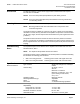
Wiring Terminals
SMIS0079R1
1
2
3
Ph
SWITCH CONNECTS 1-2 ON PRESSURE FALL
SWITCH CONNECTS 1-3 ON PRESSURE RISE
∆
p
Figure 3. Wiring Terminals.
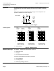
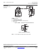
Application
Examples
∆
p
+ –
∆
p
– +
SMIS0080R1
+ Pressure upstream of filter + Pressure downstream of filter
– Pressure downstream of filter – Pressure upstream of fan on inlet
side or open to atmospheric
pressure. With radial fans, locate
at inlet center
Figure 4. Application Diagram.
Page 4 Siemens Building Technologies, Inc.