
Data Sheet for Product


3/6
Siemens Differential pressure sensor QBM4000…/ QBM4100… CE1N1919en01
Smart Infrastructure 2019-10-09
Design
The differential pressure sensors consist of:
• Sensor housing with fixing angle bar, 3-pin plug and hinged lid with sealed safety
screw
• Pressure chamber with membrane and ceramic lever
• Circuit board
• LCD display for the digital display of the sensor signal in Pa (for QBM41…D only)
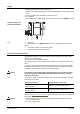
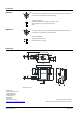
1919Z01
1 2 3 43
1 3-pin plug
2 Display window (on QBM4100-1D only) for the digital display of the sensor
signal
3 Connection nipples (see "Mounting notes")
4 Sealed safety screw for hinged cover
Mounting and installation notes
The differential pressure sensor is suited for direct mounting on air ducts, walls,
ceilings, or in control panels.
The sensor must be installed vertically.
The supplied 2 meter plastic tubing can be modified to the duct connection on the
plant.
To achieve the housing protective class indicated under "Technical data", the dif-
ferential pressure sensors must be mounted with the pressure nipple facing down.
In addition, they should be higher than the air duct probes.
If the pressure connection nipples point upward or are at a lower level than
the air duct probes, condensation can collect inside the sensor, causing
damage to the device.
The pressure tubing for the sensor nipples are connected as following to the differ-
ential pressure sensors:
On the air duct side
On the pressure sensor side
Tubing with higher pressure side
(lower vacuum)
Connect to pressure nipple "P1" or "+".
Tubing with lower pressure side
(higher vacuum)
Connect to pressure nipple "P2" or "−".
The sensor is supplied with mounting instructions.
Refer to the Manual sensor installation
from the BT download center for additional
information.
• Power supply by SELV or class 2 power supply with limited output of 15 W or
less. (UL requirement)
• Use only copper wiring
Display, setting, and
connection elements
Key
Caution
Note
Caution