
User Manual

5
Smart Infrastructure
A6V11684000_en--_b
2019-10-16
Operating elements
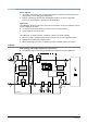
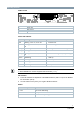
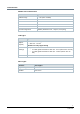
PCB overview
ON
1 2
3
4
5 6
7
8 9
LED1
A
B
C
Element Description
A Status LED
B DIP switches
C Button
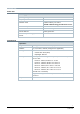
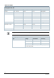
Status LED indicator
Color Flashing Function
Red Blinking, 1 sec. on, 5 sec. off ● Internal error
Red
Blinking, 0.1 second on, 1 second
off
● Invalid configuration
Orange Modulating ● Waiting for on-event addressing
Orange Blinking, 1 sec. on, 5 sec. off ● Bus communication failure
Orange
Blinking, 0.1 second on, 1 second
off
● Device not configured (factory settings)
Green Modulating ● Start-up
Green Flashing ● Normal operation
Green Flickering ● Bus communication
Blue Modulating ● Zero point reset
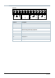
Workflows and 'How to instructions' for the DIP switches and the push button can be found
in A6V11841988. See Section Supplemental information [
➙
11].
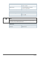
DIP switches
● ● Use DIP switches for adjustment of the Modbus address (DIPs 1 to 8) and for Modbus
line termination (DIP 9).
● The DIP switches have priority over register 'Modbus address'.
Button
Duration of operation Function
5...10 s On-event addressing
10...20 s Zero point reset
20...30 s Reset to factory setting