
User Manual

11 / 20
Siemens Central apartment unit with consumption data acquisition QAX913 CE1N2740en
Building Technologies 2016-01-30
• DHW sensor
• Air quality sensor (CO
2
sensor)
• Humidity sensor
Outputs
• Transmits heat demand (switching)
• Transmits heat demand DC 0…10 V
• Transmits cooling demand (switching)
• Transmits cooling demand DC 0…10 V
• Cooling enable
• Switching room group pump 1 - 2
• Precontroller mixing valve 1 - 2
• Step switch 1 to 3 stages
• Heat recovery bypass
• Enable exhaust hood
• Enable cooling unit 1 - 12
• Transmits changeover to summer operation
• Status output (on / off) for reporting definable events
• Window / door state output (on / off) for signaling open windows and doors
• DHW charging pump / DHW diverting valve
• Electric immersion heater
• Switching group relays 1 – 8
• Fault outputs 1 - 2
• Monitoring state
• Status outputs 1 - 4
• Water shutoff valve
• Gas shutoff valve
The central apartment unit has 8 fault inputs and 2 fault outputs which can be used
either via the universal input / universal output on the QAX913 (locally) or the uni-
versal inputs / universal outputs on the RRV912 / RRV918 heating circuit control-
lers or the RRV934 multicontroller.
Faults of external system components, such as a faulty oil tank level switch, can be
transmitted to the central apartment unit via 8 fault inputs. Each fault input can be
assigned one of the following fault types:
− Water leak
− Gas leak
− CO alarm
− Panic
− Emergency
− Fault 1 - 3
System-internal faults can be transmitted via fault outputs to external components.
The central apartment unit is capable of communicating via a wireless bus
(KNX RF) or a wire-bound bus (KNX TP).
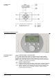
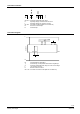
The OCI700 service tool or the OCI702 service interface can be connected to the
service interface (RJ45) located on the underside of the central apartment unit.
Fault inputs / outputs
Communication
Service interface