
User Manual

90 / 124
Siemens Synco™ living CE1C2707en
Building Technologies Function settings 23.08.2008
If 1 room unit and 2 room temperature sensors are used, the average value of
the 2 room temperature sensors is determined first. Then, the actual value of
the average room temperature is calculated based on the percentage propor-
tion set for the room unit and the room temperature sensor.
When 2 room temperature sensors are used, the average value of the 2 sen-
sors is delivered. The proportion of the individual sensors cannot be changed.
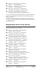
Main menu > Rooms > Room X > Room settings
> Proportion room unit:
Factory setting 50%
Your setting
Valve position cooling mode / summer operation
This determines the position to which the valve of a room is driven (0..100%)
when the plant is switched to cooling mode or summer operation. The amount
of cooling energy drawn by the individual rooms can thus be influenced.
In rooms with high humidity levels, there is risk of condensation.
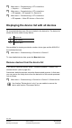
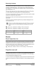
Main menu > Rooms > Room X > Room settings > Valve pos cooling:
Room number 1 2 3 4 5 6
Room name
Factory setting 0% 0% 0% 0% 0% 0%
Setting
Room number 7 8 9 10 11 12
Room name
Factory setting 0% 0% 0% 0% 0% 0%
Setting
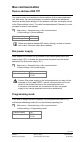
The setting has the following effect in dependence of the actuator type
used:
RRV912: 3-point actuator
The actuator exactly arrives at the set position.
RRV918 / RRV912: 2-point actuator (NC / NO)
The actuator is not controlled with setting 0..49% and remains in the
start position (for NC = 0%).
The actuator is controlled by a permanent pulse with setting 50..100%
and thus remains in the end position (for NC = 100%).
SSA955
The actuator exactly arrives at the set position.
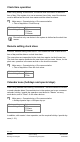
Minimum valve position Comfort
To prevent cold floors in the case of floor heating systems, a minimum valve
position (0..100%) can be fixed which is observed during Comfort periods,