
User Manual

9 / 18
Siemens HVAC central apartment unit with consumption data acquisition QAX903 CE1N2741en
Building Technologies 2016-01-30
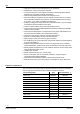
Outputs
• Transmit heat demand (switching)
• Transmit heat demand DC 0…10 V
• Transmit cooling demand (switching)
• Transmit cooling demand DC 0…10 V
• Cooling enable
• Switching room group pump 1 - 2
• Precontroller mixing valve 1 - 2
• Step switch 1 to 3 stages
• Heat recovery bypass
• Enable exhaust hood
• Enable cooling unit 1 - 12
• Transmit changeover to summer operation
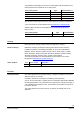
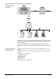
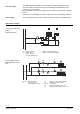
The central apartment unit communicates via a wireless bus (KNX RF) or a wire-
bound bus (KNX TP).
The OCI700 service tool or the OCI702 service interface can be connected to the
service interface (RJ45) located on the underside of the central apartment unit.
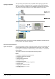
The individual wireless components are connected to the central apartment unit by
selecting the room/function to be assigned to the new wireless component and
then pressing the binding or function button on the corresponding component.
To check the connections, a list with all devices can be displayed for each room. In
addition, the corresponding device indexes are available.
Using the binding or multi-function buttons, a binding test can be triggered on the
individual devices. The central apartment unit indicates error-free connections both
optically and audibly.
The connected RF devices are monitored on a regular basis. An error message is
displayed on the central apartment unit when no transmit signal is found.
Control is no longer guaranteed if radio communications between the central apart-
ment unit and the system components to be controlled are interrupted. If communi-
cation breaks down, the position of the actuators connected to an RRV934 multi-
controller is maintained and can only be changed manually. The heating circuit
valves on RRV912 and RRV918 will open. By using the built-in room temperature
sensor, the SSA955 radiator control valves continue to control and maintain the
room temperature setpoint of 21 °C.
The ventilation plant continues to operate on the present ventilation stage for about
30 minutes and is then shut down.
System components resume normal control operation as soon as radio communi-
cations are reestablished.
Control is no longer guaranteed in the event of a power failure to the central apart-
ment unit.
If communication breaks down, the position of the actuators connected to an
RRV934 multi -controller is maintained and can only be changed manually.
The heating circuit valves on RRV912 and RRV918 will open.
By using the built-in room temperature sensor, the SSA955 radiator control valves
continue to control and maintain the room temperature setpoint of 21 °C.
The ventilation plant continues to operate on the present ventilation stage for about
30 minutes and is then shut down. The air conditioner can be operated using the
unit's own remote control.
The central apartment unit and its components resume normal control operation as
soon as power returns.
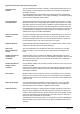
Communication
Service interface
Establish wireless
connection
Display wireless
connections
RF link test
Monitor devices
RF failure
Mains failure