
User Manual

75 / 134
Siemens Synco™ living CE1C2740en
Building Technologies Commissioning the system 13.12.2010
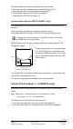
The following devices or device channels can be connected:
• Universal input B of a heating circuit controller (see page 62).
• Universal input Xx of a multi-contro
ller (see page 65).
• Door/w
indow contact wave AP 260 (see page 64).
• Water detector QFP910 (see p
age 75).
Connect water detector QFP910 (QAX913 only)
The water detector is automatically switched on as soon as the batteries are
inserted.
When switching on (power-up), the battery charge is tested.
If charged sufficiently, the green LED is lit for 2 seconds during the test.
If charge is too low for operation, the LED is lit red for 2 seconds –
provided there is enough charge.
After the battery test, the device changes directly to normal operation. The
LED goes out again.
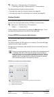
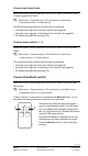
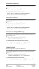
F
LED
2707Z18
Press function button F on the water detec-
tor. The LED lights up in accordance with
the battery charge (green: Bat. ok, red: Bat
not ok). Release the button when the LED
starts blinking.
F = Function button
LED = Light emitting diode
The binding LED on the device blinks green and goes out on successful bind-
ing with the central apartment unit.
The device is now connected and performs normal operation.
Connect fault outputs 1 – 2 (QAX913 only)
Inform the QAX913 central apartment unit that you want to connect a fault
output:
Main menu > Commissioning > RF connections > Faults
> Fault output 1 (or 2) > Connect device:
The following device channels can be connected:
• Universal relay output Qx of a multi-controller (see page 65).
• Universal relay
output Qx of a heating circuit controller (see page 62).