
User Manual

74 / 134
Siemens Synco™ living CE1C2740en
Building Technologies Commissioning the system 13.12.2010
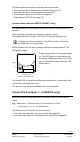
The consumption data interface is connected individually to each required
channel.
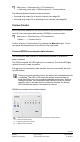
To connect a channel, select a suitable channel (P1..2 (pulse inputs), M1..3
(M-bus inputs) with the channel selection button (CH)). The channel type must
match the basic meter configuration source. The LED of the selected channel
blinks. If the selected channel is not yet connected, the binding LED flashes.
If no button is pressed for 10 minutes, the consumption data interface
returns to normal operation.
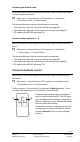
Press the function button on the consumption data interface. The LED lights
up green. Release the button when the LED starts blinking.
The consumption data interface restarts after successful connection.
The consumption data interface returns to channel selection mode and is
ready for connecting another channel.
Connect door contacts (QAX913 only)
Inform the QAX913 central apartment unit that you want to connect a door
contact:
Main menu > Commissioning > RF connections
> Doors > Door 1 (or 2) > Connect device:
The following device can be connected:
• Door/window contact wave AP 260 (see page 64).
Connect temperature sensor (QAX913 only)
Inform the central apartment unit that you want to connect a room temperature
sensor to the temperature display:
Main menu > Commissioning > RF connections
> Temperature display > Temperature X (1 – 3) > Connect device:
The following device can be connected:
• Room temperature sensor QAA910 (see page 61).
Connect fault inputs 1 – 8 (QAX913 only)
Inform the QAX913 central apartment unit that you want to connect a fault in-
put:
Main menu > Commissioning > RF connections > Faults
> Fault input X (1 – 8) > Connect device: