
Installation Instructions

Installation Instructions
Document No. 129-525
October 27, 2008
Duct Temperature Sensor
Item Number 129-525, Rev. BA Page 1 of 3
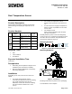
Product Description
Active output and passive resistance sensors with
plastic housing for acquiring air temperature in air
ducts.
Product Number
Type Product
Number
Sensing Output Probe
Length
Passive
Resistance
QAM2112.040 Platinum 1K Ω, 385
alpha
16 inches
QAM2112.200 Platinum 1K Ω, 385
alpha
6.5 feet
QAM2130.040
NTC 10K Ω, Type 2
16 inches
Active
Output
QAM2161.040
0 to 10 Vdc signal
[Platinum 1K Ω]
16 inches
QAM2171.040 4 to 20 mA signal
[Platinum 1K Ω]
16 inches
Required Tools
• Drill
• 7/8-inch drill bit
• Screwdriver
Expected Installation Time
45 minutes
Prerequisites
• Field wiring must be pulled to utility box near
installation point. (14 AWG to 16 AWG)
• Mounting Clamps (AQM63.3), if required by
mounting configuration.
Installation
Depending on the use, locate the duct sensor as
follows:
• For supply air temperature control:
If the fan is located after the last air handling
unit, install downstream from the fan.
Otherwise, mount after the last air handling
unit with a minimum distance of 1.6 feet
(0.5 m).
• For exhaust air temperature control:
Always mount upstream of the exhaust air
fan.
• As a limit sensor for supply air temperature:
Mount as close as possible to the air outlet
into the room.
• For dewpoint control:
Mount sensor immediately after the spray
trap of the air washer.
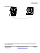
Manually bend the probe so that it lies diagonally
across the duct or in equally spaced windings across
the entire duct cross-section. The probe must not
touch the duct wall (see Figure 2).
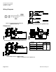
Mounting Positions
Figure 1. Permissible Mounting Positions.
Mounting Examples
Figure 2. Installation.
Mounting Instructions are printed on the packaging.
The installation is now complete.