
Installation Instructions

Document No. 540-1022
Installation Instructions
October 26, 2016
Siemens Industry, Inc. Page 3 of 6
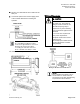
6. Plug the room temperature sensor cable into the
RTS port.
7. Connect the power trunk. DO NOT apply power
to the controller without first consulting the
specialist.
NOTE:
As a standard grounding procedure,
ensure that a ground wire is connected
directly from neutral of the 24Vac
secondary (the side that connects to
the "C" terminal of the TEC) to earth.
The installation is complete.
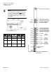
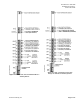
Wiring Diagrams
CAUTION
The controller’s DOs control 24
Vac loads only. The maximum
rating is 12 VA for each DO. An
external interposing relay is
required for any of the following:
• VA requirements higher than the
maximum
• 110 or 220 Vac requirements
• DC power requirements
• Separate transformers used to
power the load.
(for example part number 540-147,
Terminal Equipment Controller
Relay Module)
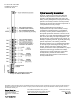
Wiring for AI with a 4 to 20 mA Sensor.
NOTE:
If the voltage/current switch is set to
current and a 4 to 20mA sensor is
connected to an AI, then special wiring
requirements must be followed.