
Installation Instructions

Installation Instructions
Document No. 540-1022
October 26, 2016
TEC Dual Duct – Two Air Velocity
Sensors Controller
Item No. 540-1022. Rev. EA Page 1 of 6
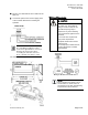
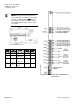
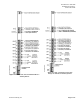
Generic Controller I/O Layout. See Wiring Diagram for application specific details.
Control Applications
2237 and 2238
2267 through 2269
Product Description
These instructions explain how to field install or
replace a TEC Dual Duct Controller - Two Air
Velocity Sensors.
Product Numbers
TEC Dual Duct Controller -
Two Air Velocity Sensors
540-506N
TEC Dual Duct Controller -
Two Air Velocity Sensors with
Autozero Module
540-507N
Shipping carton includes a controller assembly, a
mounting rail, and two self-tapping/drilling screws.
CAUTION
Keep the unit in its static-proof bag
until installation.
Otherwise you run the risk of
damage to the printed circuit board
from electrostatic discharge.
Accessories
Low cost temporary temperature
sensor, 10K thermistor with RJ11,
that enables space control if the
permanent room or duct sensor is
not installed (pack of 25).
540-658P25
Duct Temperature Sensor, NTC
100K Ω Type 2, 3" Probe for
Commissioning Only
QAM1035.008P50