
Installation Instructions

Document No. 540-1024
Installation Instructions
October 26, 2016
Siemens Industry, Inc. Page 3 of 5
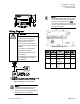
Wiring Diagram
CAUTION
The controller’s DOs control 24
Vac loads only. The maximum
rating is 12 VA for each DO. An
external interposing relay is
required for any of the following:
• VA requirements higher than the
maximum
• 110 or 220 Vac requirements
• DC power requirements
• Separate transformers used to
power the load.
(for example part number 540-147,
Terminal Equipment Controller
Relay Module)
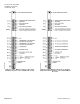
Wiring for AI with a 4 to 20mA Sensor.
NOTE:
If the voltage/current switch is set to
current and a 4 to 20mA sensor is
connected to an AI, then special wiring
requirements must be followed.
NOTE:
When wiring any actuator that uses a 0 to
10V control signal and ties AC neutral to
DC common, an additional wire
must
connect the actuator AC neutral to the DC
common of the PTEC/TEC AO being used
to control the actuator.
24 Vac Modulating Control.
Actuator
Symbol
TEC
Connection
Function
Terminal
Connection
Standard
Color
1
H
Supply (SP)
G
Red
2
C
Neutral (SN)
G0
Black
8
AO3 – 15
(+)
0 to 10V
input signal
Y
Gray
--
C to AO3
16 (-)
Common
jumper
--
--